According to the solar cell assembly characteristics, the welding method conforming to the flexible assembly system is selected. According to the movement characteristics of the grab robot and the welding manipulator, the motion path schemes of the two are designed separately. By rationally simplifying the motion model, the motion path analysis and calculation are performed separately for the grab robot and the welding robot to optimize the motion path of the robot to improve product quality and Productivity.
Solar cells are devices that convert solar energy into electrical energy. Large solar panels formed by welding and assembling multiple solar cells can increase the total amount of solar energy collected and improve the utilization of solar energy. The solar cell flexible assembly system includes a grasping robot and a welding robot, and can realize automatic assembly of the solar battery according to the size parameters and characteristics of the solar battery.
1. Welding robot welding scheme
As shown in Fig. 1, in the welding process of the solar cell, two adjacent solar cell electrodes need to be overlapped, that is, the positive electrode of one battery is connected with the negative electrode of another battery, and the welded joint region is completely embedded in two. In the middle of the block battery, the heating of the target welding area is very inconvenient, and it is not suitable to use the fusion welding method. If pressure welding is used, the solar cell electrode is easily deformed under high temperature and high pressure, which has an adverse effect on the performance of the solar cell.
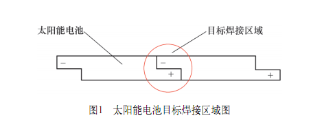
Therefore, the welding of solar cells is performed by brazing.
2. Research on the motion path of grabbing robot
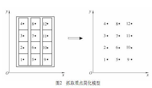
Grab the manipulator mainly plays the role of grasping and arranging the solar cells. The solar cells are arranged according to the predetermined design requirements; the robot grabs 12 solar cells and arranges them in 4 rows and 3 columns.
Based on the global coordinate system, when the grab robot is working, the initial position of the solar cell is set as the coordinate origin; when the shape of the solar cell is a regular object, the projection in the xoy plane is a regular rectangle; when studying the path motion scheme of the grab robot Each solar cell can be simplified into a mass point in the xox plane, which is the geometric center point of the solar cell, and the moving path of the grabbing robot can be simplified into the model shown in FIG.
Since the length and the width of the solar cell are different, when the velocity vx in the x direction is the same as the velocity vy in the y direction, the time required for the gripping robot in the x and y component directions is different. When vx is much larger than vy, the grab robot needs to move a distance in the y direction after completing the amount of movement in the x direction; when vx is much smaller than vy, the opposite is true.
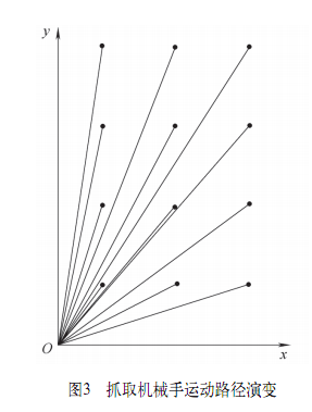
According to the principle of the shortest line between two points, the most ideal motion path of the grab robot in the xoy plane is linear motion. During the same movement time, the x-axis and the y-axis can reach the end point at the same time, which not only guarantees the shortest time, but also guarantees the shortest path, that is, the optimal motion path is selected between the two fixed points. The process of grabbing the 12 batteries by the robot evolves into a linear motion from the same origin to 12 different end points, as shown in Figure 3.
Considering that the two adjacent solar cells are stacked and overlapped, they cannot be randomly placed and placed in accordance with a certain sorting order to complete the predetermined requirements. Taking the first array of solar cells as an example, if the first captured solar cell is placed at number 1, the second captured solar cell can be placed at number 2 or number 5. If the solar cell captured for the first time is placed at the number 2 position, the position of the number 1 is not easy to place the solar cell block; if the solar cell captured for the first time is placed at the position of 3 or 4, it will appear. Adjacent solar cells are difficult to grasp and place. For the same reason, the above arrangement problem also occurs for the arrangement of the solar cells of the second column and the third column.
Based on the above analysis, the grasping robot preferentially grabs the positive direction along the x-axis or the positive direction of the y-axis when grasping; that is, if the solar cell is grasped in the positive direction of the x-axis, the optimal position of the solar cell is placed. The order is 1, 5, 9, 2, 6, 10, 3, 7, 11, 4, 8, 12 (battery position number); if the solar cell is grabbed in the positive direction of the y-axis, the optimal position of the solar cell The order of placement is 1, 2, 3, 4, 5, 6, 7, 8, 9, 10, 11, 12. In summary, the grab robot has multiple motion paths, and the motion paths are optimally arranged along the x-axis or the y-axis.
The motion path shown in FIG. 4 is a sequential grasping arrangement along the positive direction of the y-axis. The station 01 is the initial position of the grab robot (also the reset position), the station 02 is the battery position; the A1 process is to move the grab robot from the station 01 to the station 02, and prepare the movement for the robot to arrange the solar cells; The process is to grab the robot's working process. Grab the solar cells one by one. When the robot finishes grasping and arranging the solar cells, it will go back and forth to the station 02 to grab the next solar cell and arrange it.
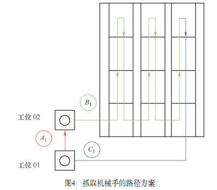
After the grab robot completes the row of batteries, the second and third rows of solar cells are automatically arranged according to the set path, leaving a gap between the two rows. After the grabber completes its gripping and aligning work, it returns along the path shown in the C1 process. If you need to continue working, return to station 02; if you no longer need to work, return to station 01 reset to facilitate the next work.
3. Research on the motion path of welding manipulator
The welding manipulator mainly welds two adjacent solar cells together to complete the welding process. The solar cells are arranged in 4 rows and 3 columns, and welding is required 9 times to complete all the welding processes. The welding position is simplified into 9 mass points, and then 9 mass points are connected in series, which is the moving path of the welding robot during the welding process, as shown in Fig. 5.
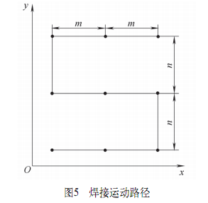
According to the "S" type route that the robot walks during the welding process, the total distance S1 that needs to be taken when the welding is completed 9 times can be calculated, which is easy to obtain:
S1=6m+2n
The specification parameters of the solar cell are known, the length dimension is a, the width dimension is b (a>b), and the gap between the two columns of cells is δ, then:
m=b+δ, n=a
The total distance S1 taken by the robot to complete the welding process is:
S1=2a+6b+6δ
After the path planning of the grab robot and the welding manipulator is completed, under the control of the PLC system, the collaborative work of the two is completed, and the flexible assembly function of the solar cell is realized.
4. Conclusion
The solar cell flexible assembly system has the characteristics of simple structure, accurate motion, sensitive response and high control precision. The research on the movement path of the system manipulator can help improve the assembly quality and production efficiency of the solar cell. The path of motion along the positive direction of the x or y axis is optimal; and the "S-type" motion path scheme is designed for the welding manipulator, which meets the motion requirements of the welding manipulator.
Guangzhou Yunge Tianhong Electronic Technology Co., Ltd , https://www.e-cigarettesfactory.com