Increase primary current, increase secondary voltage and ignition energy, improve high speed performance. Reduce contact sparks, extend contact life and overcome mechanical defects. Easy to maintain, good starting performance. The mixture burns completely and there is less pollution. Conducive to the development of multi-cylinder, high-speed cars.
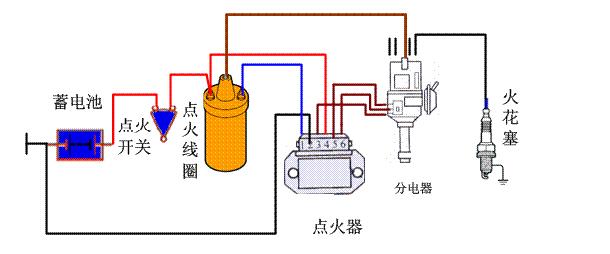
The role of the car ignition system1. The ignition system turns the low voltage of the power supply into a high voltage, and sends them to each cylinder in turn according to the ignition sequence of the engine to ignite the compressed gas mixture.
2, can adapt to changes in engine operating conditions and conditions of use, automatically adjust the ignition time, to achieve reliable and accurate ignition;
3. Manually calibrate the ignition timing when changing the fuel or installing the distributor.
Car Ignition System Circuit Diagram (1)Hall electronic ignition device circuit diagram, as shown.
Tu Hall electronic ignition device circuit diagram
Electronic igniter electrical schematic: Hall-type electronic ignition device uses integrated circuit igniter, with current limiting, ignition angle control, shutdown power protection, closed angle control and other functions, as shown in the circuit.
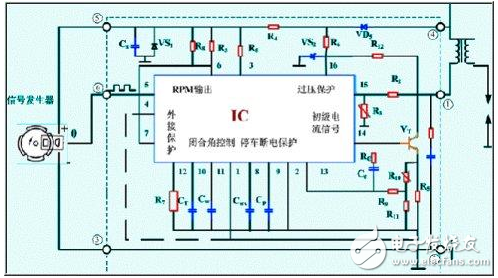
Figure IC Igniter circuit diagram
Working principle: Turn on the ignition switch, the engine rotates, the Hall signal generator of the distributor triggers the blades of the impeller, and periodically passes through the air gap of the sensor. When the blade enters the air gap, the magnetic field on the Hall element is shielded, no Hall voltage is generated, and the signal voltage output by the Hall signal generator is a high voltage. This signal passes through the igniter sockets 6 and 3 to enter the igniter, The internal circuit of the igniter makes the high-power triode VT conduct, and connect the primary circuit. Its circuit is: Battery "+" → Ignition switch → Ignition coil primary winding → Igniter power tube → Ground → Battery "-" pole. When the impeller is triggered to leave the air gap, the magnetic field is applied to the Hall element to generate a Hall voltage, the signal generator outputs a low voltage, the igniter power tube VT cuts off, the primary loop is cut off, the secondary voltage is high, and the spark plug flashes. Ignite the mixture.
Car ignition system circuit diagram (II) photoelectric electronic ignition device(1) Signal Generator
Structure: The signal generator consists of a signal rotor, a light source, and an optical receiver, as shown in the figure. The light source is a potassium-on-cadmium light-emitting diode. Invisible light beams that emit close to infrared frequencies are collected through the hemispherical lenses in front of them, limiting the width of the light. The light source emitted by the light emitting diode is received by a photodiode as a light receiver.
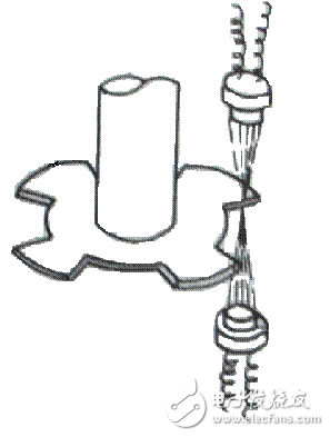
Photoelectric signal generator
Features: The output voltage amplitude is not affected by the engine speed, high reliability.
Working condition: The signal rotor is driven by the distributor shaft. The number of blades (shadows) on it is equal to the number of cylinders in the engine. When the signal rotor rotates with the distributor shaft, the blades and the gap continuously pass between the light source and the photodiode. The phototube emits a low level under the illumination of the light source. In the absence of a light source, the output is high, so a pulse signal is generated. After being processed by the electronic controller, the ignition signal is output.
(2) Electronic ignition device
Circuit diagram: Photoelectric electronic ignition device circuit diagram as shown.

Figure Photoelectric electronic ignition device circuit diagram
Analysis of the working situation: The gallium arsenide infrared diode GA is an infrared light source, and the silicon photodiode VT1 is a receiver. When the engine is working, the shading plate rotates with the distributor shaft. When the gap on the shading plate passes through the light source, the infrared ray shines on the silicon photodiode VT1 through the notch so that it is turned on → VT2 is on → VT3 is on → VT4 is off → VT5 is on, and the primary circuit is connected. When the solid part of the shading plate hides infrared rays, VT1, VT2 turn off → VT3 turns on → VT4 ends. The primary circuit is cut off and high voltage is generated at the secondary.
Ignition system precautions
1. Shut off the ignition switch when parking, checking or performing necessary dismantling;
2. The battery should be in a fully charged state. The wires in the ignition system should be connected well. In particular, the grounding must be good.
3. When replacing the ignition system parts, generally the same model should be replaced to avoid mixed use of various models. It is not possible to replace the special ignition coil with the ordinary ignition coil.
4. When welding on the vehicle, first remove the battery wiring.
5. When flushing the vehicle, avoid splashing water into the electronics.
6. When judging the fault, do not use the method of scraping the fire to test the electricity;
7. Never disassemble the battery while the engine is running.
Car ignition system circuit diagram (3)Automotive ignition system designed with CD.
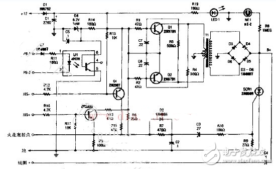
The core of CD4MAX is a self-oscillation multivibrator composed of Q1 and Q2. The oscillator is used to drive the step-up transformer T1, and the output voltage of T1 is rectified by D3 to D6 to charge the capacitor C4. When the spark plug closes after the charge is completed, a small voltage is sent to the gate of SCR1 to make it turn on quickly, and the charge of C4L is immediately released to the ignition coil. The circuit also includes several optional branches to satisfy The need for different types of ignition devices.
X15+ and X15—Used for different starting circuit configurations for non-contact breaker igniter systems. R6 is not used in these systems and can be removed. According to the polarity of the sensor, optocoupler U1 (pin 4) can be used with X15+ With the use of.
Please note that the voltage on this system is up to 60-70kV, so proper safety precautions are required.
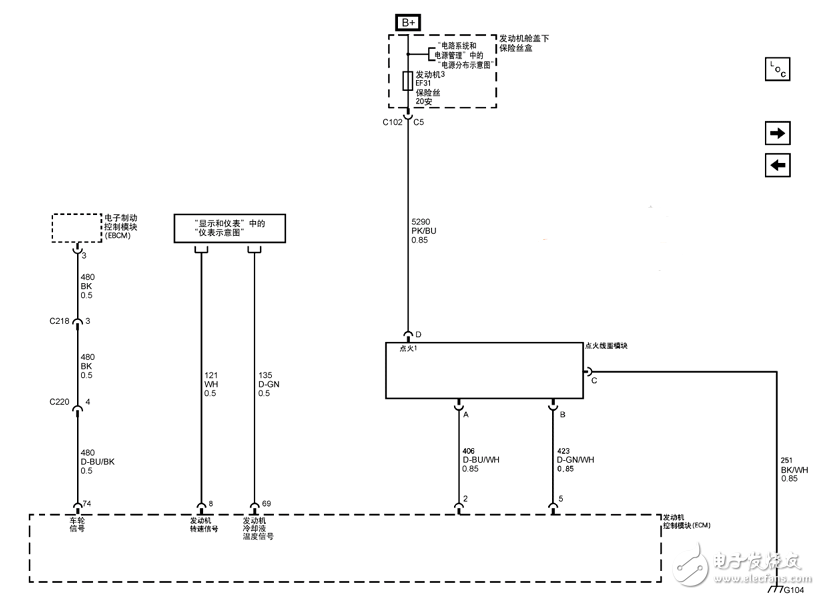
Car ignition system circuit diagram (4)Epistar engine data sensor-ignition system circuit diagram is as follows:
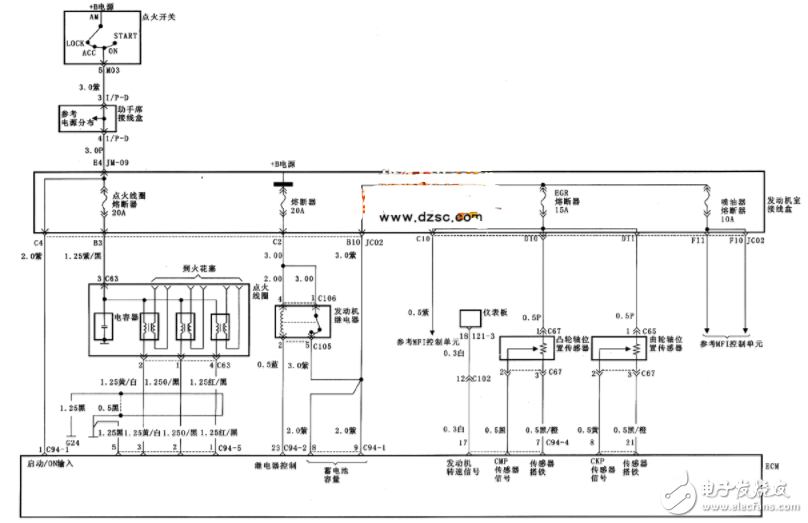
Beijing's modern Sonata ignition system circuit diagram is as follows:
With the development of the times, the consumption level of people is gradually increasing. At the same time, people's entertainment methods are beginning to diversify, especially for modern young people. As a result, different kinds of electronic products are starting to be in people's lives, and the booming Electronic Cigarette industry reflects this.
Described including the upper shell, the upper shell at the top of the smoke outlet, as described in the bottom of the upper shell with airway, described with the smoke outlet in the airway and also to match the upper shell, the lower part of the shell described the airway in the direction of the lower shell extension, as described in the lower shell near one end of the upper shell is equipped with oil mouth, described the lower shell with batteries, described at the bottom of the bottom shell has come in The air port is provided with an oil storage bin in the lower shell, and the air passage passes through the oil storage bin and is provided with a heating atomization bin at one end away from the smoke outlet. The utility model has beneficial effects: it can meet the smoking habit of different users, avoid the premature end of the use experience caused by excessive consumption of smoke oil, and indirectly prolong the service time and life of the product.
Refillable E-Cig Oem,Refillable Vape Pod,Refillable Vape Pen Oem,Refillable Mod Oem
Shenzhen MASON VAP Technology Co., Ltd. , https://www.cbdvapefactory.com