Carrier Aggrega (TIR) ​​concept
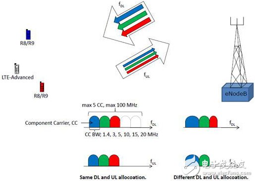
Figure 1. Concept of carrier aggregation (Carrier AggregaTIon)
Carrier aggregation (Carrier aggrega TIon) is used in LTE-Advanced to increase the signal bandwidth, thereby increasing the transmission bit rate.
In order to meet the LTE-A downlink peak speed of 1 Gbps and the uplink peak speed of 500 Mbps, it is necessary to provide a transmission bandwidth of up to 100 MHz. However, due to the scarcity of such a large bandwidth continuous spectrum, LTE-A proposes a carrier aggregation solution.
Carrier Aggrega (C) aggregates two or more Carrier Carriers (CCs) to support a larger transmission bandwidth (up to 100 MHz).
The maximum bandwidth per CC is 20 MHz
In order to efficiently utilize fragmented spectrum, CA supports aggregation between different CCs (Figure 2).
· CCs of the same or different bandwidth
· Adjacent or non-contiguous CCs in the same frequency band
· CCs in different frequency bands
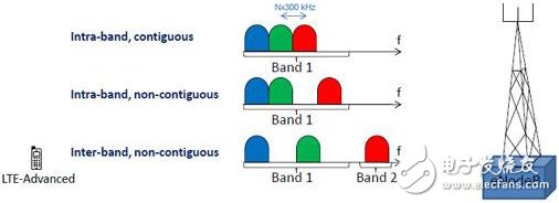
Figure 2. Several forms of carrier aggregation
From the point of view of baseband implementation, there is no difference between these situations. This mainly affects the complexity of the RF implementation.
Each CC corresponds to a separate cell. In a CA scenario, it can be classified into the following types of cells:
Primary Cell (PCell): The primary cell is a cell operating on the primary frequency band. The UE performs an initial connection establishment process in the cell or starts a connection re-establishment process. The cell is indicated as the primary cell during handover;
Secondary Cell (SCell): A secondary cell is a cell operating on a secondary frequency band. Once the RRC connection is established, the secondary cell may be configured to provide additional radio resources;
Serving Cell: The UE in the RRC_CONNECTED state, if there is no CA configured, there is only one Serving Cell, that is, PCell; if the CA is configured, the Serving Cell set is composed of PCell and SCell;
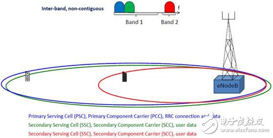
Figure 3. Several Celles for Carrier Aggregation (CA)
The role of carrier aggregation:
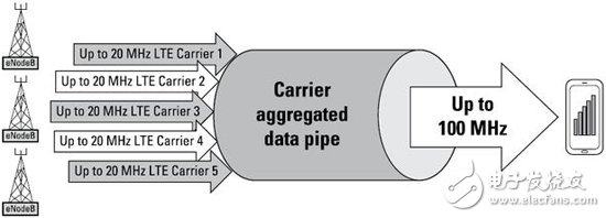
Figure 4. CA combines multiple LTE carrier signals to increase data rate and improve network performance.
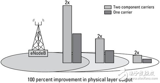
Figure 5. CA technology improves carrier performance.
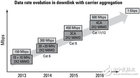
Figure 6. Relationship between 3GPP data rate evolution and CA
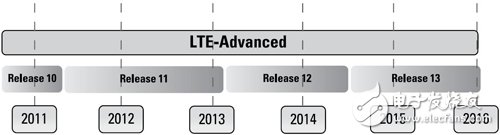
Figure 7. 3GPP Release Agreement Schedule
Carrier aggregation (Carrier Aggregation) design difficulties
The design challenges for downstream CA include:
· Downlink sensitivity
· Harmonic effects
· The desense (sensitivity deterioration) challenge encountered in CA RF design
If you design a separate duplexer for each band, ensure that the downlink band is unaffected; however, connecting two duplexer paths can affect the filter characteristics of the two duplexers, causing you to lose system sensitivity. The isolation between the transmit and receive paths required for runtime is required.
In the case of some CAs with larger frequency spacing between the two frequency bands (eg, a CA combination between the middle and low frequency bands), a separate duplexer can be added. A diplexer (antenna duplexer or antenna splitting filter) is inserted between the antenna and a separate dedicated duplexer in the two frequency bands.
In the CA architecture, some designers are using multiplexers (multiplexers) and hexiplexers (duplexers) instead of duplexers. If a multiplexer is needed, each individual filter in the device requires complex development because it is not as simple as placing two filters in a package, because we expect them to be a unified whole. Work inside the device. Designers must ensure that the filters in each band work together in the multiplexer. Although the development of multiplexers is more challenging, it simplifies the work of RF front-end designers and increases the available PC board area. The following figure depicts a simple front end showing duplexers and diplexers (antenna duplexers or antenna split filters).
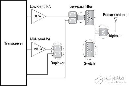
Figure 8. RF front end with duplexers and dividerrs
Influence of generated harmonicsHarmonics are generated by nonlinear components such as the output stage of a transceiver, power amplifiers (PAs), duplexers, and switches. In the development of component components, designers must carefully weigh the performance standards of various devices to help reduce the effects of harmonics and other intermodulation products generated by these devices.
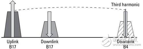
Figure 9. High switching isolation and harmonic filtering are required to mitigate the sensitivity degradation caused by harmonics.
The desense (sensitivity deterioration) challenge encountered in RF front-end designWireless RF signals in multiple bands may interfere with each other due to insufficient filter rejection. This means that if the isolation or cross-isolation between the transmit and receive paths is insufficient, the probability of desensitization in the CA application is high. The following pictures illustrate several typical desense phenomena.
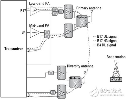
Figure 10, B17 The third harmonic of the UL signal is coupled with the DL of B4, causing desense
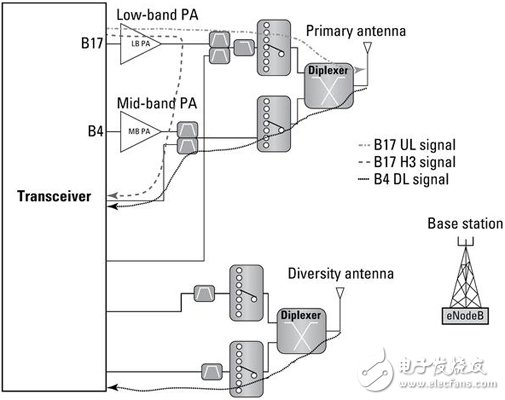
Figure 11. Harmonic problems caused by insufficient isolation of PCB board traces
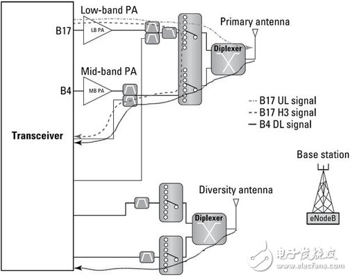
Figure 12. Insufficient isolation between the internal low frequency or intermediate frequency band switching paths may cause harmonic problems.
Uplink CA design challengesIn the Chinese market, TDD is the main driver of uplink (UL) carrier aggregation. In 2014, China Telecom and Nokia Networks announced the launch of the world's first FDD-TDD CA device chipset. The development uses FDD Band3 to improve LTE coverage while supporting improved TDD Band 41 to increase throughput.
The Intra-band CA is the simplest implementation of different uplink CA types, so it is the first step for most operators to implement uplink CA.
LinearIn-band uplink CA signals offer many challenges for mobile device designers because they can have higher peaks, greater signal bandwidth, and new RB configurations. Even if the signal power can be retracted, the PA design must be adjusted to achieve very high linearity. Adjacent channel leakage (ACLR), intermodulation products of discontinuous RBs, spurious emissions, noise, and effects on receive sensitivity must be considered.
The uplink inter-band CA combines transmit signals from different frequency bands. In these cases, the maximum total power transmitted from the mobile device does not increase, so for each of the two transmit bands, each band carries half of the normal transmission or 3 dB less than the transmit power of the non-CA signal.
Since different PAs are used to amplify signals of different frequency bands, and the respective transmission powers are reduced, the linearity of the PA is not a problem. Other front-end components, such as switches, must handle high-level signals from different frequency bands and may mix or create new intermodulation products. These new signals can interfere with an active cellular receiver and even interfere with other receivers on the smartphone, such as GPS receivers. In order to manage these signals, the switches must have very high linearity.
80 Plus Gold
Boluo Xurong Electronics Co., Ltd. , https://www.greenleaf-pc.com