Automakers face the challenge of making cars safer, smarter and more energy efficient, which in turn drives the advancement of automotive electronics. Electronic products have always been the fastest growing segment of automotive content, surpassing mechanical, pneumatic and hydraulic power.
This article refers to the address: http://
Embedded system designers are constantly developing new electronic control modules (ECMs) to meet the car's desired driver's capabilities. The growing demand for greater safety, comfort, confidentiality and driver information applications is the main reason for the growth of automotive electronics. This growth is also spurred by consumer preferences and government regulations, and because of the fierce competition in the global market, OEMs are very sensitive to costs.
Flash-based, highly integrated power management microcontrollers (MCUs) are not only the foundation of ECM, but also help embedded system designers overcome the major challenges of implementing new features. These challenges range from power and space constraints to ECM connectivity for diagnostic functions while still being cost effective. Subsystem vendors have been working with their suppliers to develop reliable, cost-effective and innovative solutions. Resolving these challenges with competitive solutions is a common approach used by current automotive embedded system designers.
Challenge 1: Meet the power budget
As more and more electronic products penetrate into automotive interior applications, the number of ECMs continues to increase, which makes the car's power budget very tight. Some higher-end cars may even have more than 80 ECMs, which means that the current load is also increasing. One way to overcome this challenge is to increase the battery size to meet ever-increasing power requirements. However, in environments where space is limited and weight is also a key factor, the use of larger sized batteries is not always a good compromise because it has a negative impact on fuel consumption.
A better alternative is to reduce the power requirements of these ECM modules when the car engine is turned off. As the car is turned off with more power loads, such as automatic door opening (Keyless Entry) and infotainment systems, car OEMs have begun to tighten the power budget at the time of flameout, requiring that each ECM's power budget does not exceed 1 mA. The Power Management Microcontroller family empowers embedded designers to deliver high-value, energy-efficient work without sacrificing performance.
Power management microcontrollers eliminate the need for external components, providing designers with on-chip flash memory, maximum system efficiency, greater system robustness, and lowest cost and board space. Multiple power management modes give designers the flexibility to switch between modes and integrate energy-saving programs into their applications. These innovative solutions have been developed to enable microcontrollers to perform power management tasks more efficiently, and are a powerful tool popular with automotive embedded system designers. It is the designer's desire for a microcontroller to provide flexible power management techniques over its operating frequency range. Power management microcontrollers must be versatile, giving designers a wide range of technical feasibility and cost-effective options to address the complex challenges associated with reliable low-power operation in advanced automotive body control systems. Table 1 summarizes the power management features of the microcontroller, allowing designers to refer to the microcontroller family for their body control electronics modules.
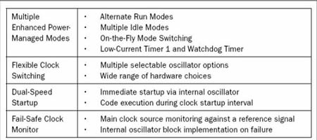
Microcontroller power management
The ideal microcontroller family should provide designers with a platform to create innovative energy-saving programs. The platform should include a wide range of on-chip peripherals such as an optional oscillator and multiple crystal modes, an external clock mode, an external RC oscillator mode, and an internal oscillator block that can generate multiple clock frequencies under software control. Figure 1 is an example of energy savings based on a power management microcontroller.
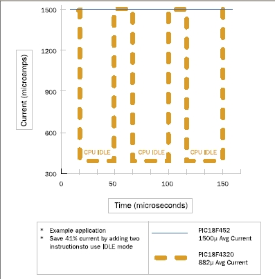
An example of energy saving based on power management microcontroller
Low power and reliable operation are the main considerations for body control ECM development. Figure 2 shows the range of functions required for a power management microcontroller to achieve flexible control and optimal low-power operation to minimize overall current consumption and reduce power consumption.
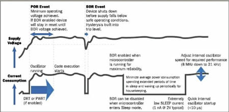
Power management microcontrollers enable flexible control and optimal low-power operation to minimize overall cost of operation and reduce power consumption
The main on-chip building blocks for reliable low-power operation include an internal oscillator, sleep mode, power-on reset (POR), brown-out reset (BOR), device reset timer (DRT), and power-on reset timer ( PWRT). The internal oscillator is critical to meeting the performance requirements of a power management microcontroller. The internal oscillator is adjustable in performance and stable over voltage and temperature ranges, providing a wide range of options, allowing designers to more tightly control ECM power consumption, adapt to online changes, reduce external component count, and ultimately reduce Cost, improve performance.
During inactivity, sleep mode puts the microcontroller to sleep, minimizes average power consumption, and only activates when a specified task must be performed. Both the DRT or PWRT are based on an internal timer that keeps the microcontroller in a reset state and leaves enough time for the supply voltage and internal oscillator to stabilize. The POR is based on internal circuitry to ensure that the microcontroller's supply voltage reaches a minimum voltage before releasing the DRT. When the supply voltage spike is below the rated operating voltage, the BOR ensures reliable operation of the microcontroller by resetting the microcontroller. Power management microcontrollers give designers the flexibility to create embedded solutions with minimal current consumption and lower power consumption for their projects.
Challenge 2: Meet performance requirements in a space-constrained environment
The main reason for the growth of body control ECM applications is that automakers want to meet the functional requirements of car target opening. The result of the increase in ECM is that the available space is becoming more and more limited. Designers expect the use of microcontrollers to achieve high on-chip peripheral integration (both digital and analog) to support the overall goal of space saving. Figure 3 shows the range of on-chip peripherals that can be implemented using the current family of controllers on the market.
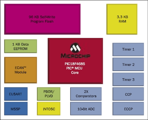
Take advantage of the range of on-chip peripherals that can be implemented with the current family of controllers on the market
The microcontroller architecture is critical to supporting software migration. The industry's popular microcontroller architecture supports multiple migration paths, where their upward compatibility optimizes processing efficiency and performance. For example, the PIC microcontroller architecture incorporates RISC functionality and an improved Harvard dual-bus architecture. Instructions and data are transferred over separate buses, eliminating bottlenecks and improving overall system performance.
Powerful portability supports the reusability of engineering modules, which helps save development time and overall cost. Compatibility is important for the reuse of microcontroller designs. The standardized pinout of the microcontroller family supports the development of code libraries that can be used in a wide range of applications and is very popular with designers. A microcontroller architecture that provides socket, software, and peripheral compatibility provides designers with exceptional flexibility. For example, each pin can be used for several peripheral functions, so designers can add or switch between different functions without having to change the printed circuit board design. The end result is to minimize or even eliminate the cost of redesign.
Reusing proven engineering modules not only saves time and money, but also directly improves overall system quality, as engineers can draw on previous design experience and apply existing results in current designs. Ultimately, compatibility and reusability increase overall product development efficiency, which is critical in the absence of experienced embedded designers.
Challenge 3: Provide cost-effective connectivity for multiple ECMs in the car
The growing number of ECMs inside the car creates an automotive network environment. The body control electronics module enhances the comfort and safety of the occupants in the car. For automakers, advanced body control modules are a key element in producing smarter, more reliable and safer cars. The body control electronics module simplifies vehicle operation and frees the driver from auxiliary activities, thereby increasing the safety factor of the car. The network is a key part of the in-car electronic architecture. A single network protocol cannot meet the requirements of many applications across the body. The challenge for automotive electronics system architects is to define the appropriate network protocols to achieve the required performance within the target budget. Therefore, the chosen network protocol must match the appropriate application that meets the price/performance requirements.
Once the auto architect defines it, meeting the cost budget becomes a requirement that embedded system designers must meet. Figure 4 shows the multiple communication networks employed within the vehicle and the associated costs of implementing each node. The two most popular automotive networks today are Controller Area Network and (CAN) and Local Internet (LIN).
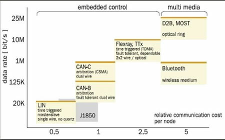
Multiple communication networks used in the car
CAN provides a multi-master system that supports the development of intelligent redundant systems. In such a network, if there is a problem with one network node, it will not affect the network function. The message is still broadcast over the web. All nodes are able to receive, read, and determine if they are related to themselves and if action is required. In this environment, data integrity is guaranteed because all nodes in the system use the same information. Data integrity is guaranteed by error detection mechanisms and error message retransmission mechanisms.
The LIN protocol is a complete communication specification for smaller in-vehicle networks. The specification includes protocol definitions and physical layer definitions, as well as development tools and application software interface definitions. For applications such as automotive switches, smart sensors and actuators that do not require as much bandwidth and versatility as CAN, LIN offers a cost-effective communication network. The LIN communication protocol is based on the SCI (UART) data format and uses a single-master/multi-slave mode with a single-wire 12V bus. Node clock synchronization does not require a stable time base.
Given that LIN is primarily used for low-end applications, two factors are critical: first, the communication cost per node must be quite low compared to CAN; second, the performance, bandwidth, and versatility of CAN are not required. Compared to CAN, LIN's cost savings come mainly from: 1. Single-wire transmission, 2. Hardware and software can be implemented at low cost within the chip, 3. The slave node does not require the use of crystal or ceramic resonators. The main features of the LIN and CAN protocols are shown in Table 2.
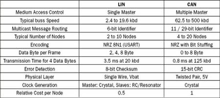
Main features of the LIN and CAN protocols
Embedded controllers now have microcontrollers with on-chip peripherals that support CAN and LIN communication protocols. Gateway microcontrollers are used for switching between high-speed and low-speed CAN buses, as well as between low-speed CAN and other networks such as multimedia, fiber point-to-point networks, and media-oriented system transport (MOST) protocols. LIN is a sub-bus network that can be directly connected to a CAN network. Integrated microcontrollers that support these communication protocols can help reduce component count and system cost as the number of ECMs in the car continues to increase.
Summary of this article
As the demands for comfort and safety of modern cars continue to increase, cars are becoming more intelligent. For embedded system designers, microcontrollers are an essential tool for solving the following challenges with automotive electronics modules: implementing a cost-effective ECM network in the car; providing the required functionality in a predetermined limited space; Meet the predetermined power budget.
The family of power management microcontrollers with a large number of integrated peripherals gives designers the flexibility and choice to create innovative, compact and cost-effective solutions for automotive consumers. expect. For ECM, full flexibility is an important factor in reducing time to market.
Nowadays, the function and appearance of mobile phones are similar, but the charging interface is not unified. The Android camp has Micro USB and Type-C ports, while the iPhone camp has Lightning. Different charging ports use different charging cables, which is very unfriendly for users who often need to use multiple phones. To solve this awkward situation, the three-in-one data cable was born. What is the three-in-one data cable? Three-in-one data cable means that one data cable includes Micro Usb Cable, USB Cable For Iphone and Usb Cable Type C. So one data cable can be used by all mobile phones.
Three-in-one data line is also known as multifunctional data cable. In the original data cable, the combination scheme is added, and the combination PCB is configured, which can support a variety of equipment and avoid the trouble of frequently looking for data line. It combines Lightning, a 30-pin port, and a Micro USB port, and is compatible with multiple devices. It can connect to any smartphone or tablet, including iPhone, iPad, Samsung, etc.
From the technical point of view, the three-in-one data cable does have a strong advantage. With continuous development and improvement, three in one data cable products in the original data cable appearance with woven cloth, will also add a light color on the three in one data cable, so that the data cable function is stronger and more exquisite, more and more people accept and buy. In the era of big data,the 3 In 1 Usb Cable can be said to have deeply affected our work and life. We believe that with the technical development of 3-in-1 mobile phone data cable, it will bring us more convenient transmission experience.

3 In 1 Usb Cable,3 In 1 Data Cable,3 In 1 Usb C Cable,3 In 1 Universal Cable
Henan Yijiao Trading Co., Ltd , https://www.yjusbhubs.com