Adding two infrared remote control interfaces to the single-chip control system, and using the handheld infrared remote control to assist or replace the operation of the keyboard, brings great convenience to the user. Based on our actual development experience, this section introduces the performance of the infrared remote control transmitting and receiving chip BA5048 and BA5050 and its interface circuit with the 51 series MCU system, and gives the software identification key code method and assembly subroutine.
1. 36.1 Characteristics of infrared remote control transmitting and receiving chip BA5048 and BA5050
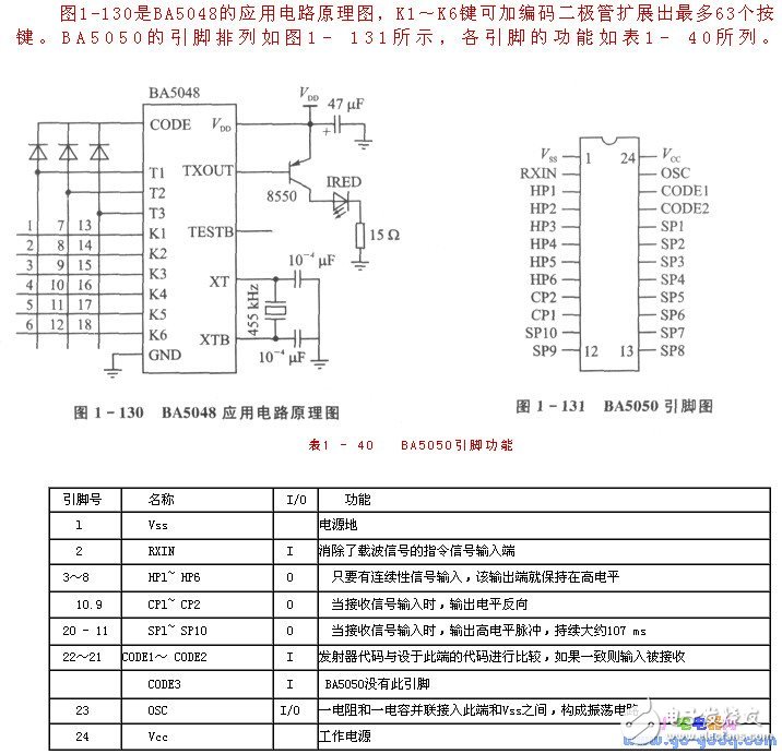
The BA5048 and BA5050 are paired infrared remote control transmitter receiver chips. BA5048 is a transmitter with CMOS structure, low power consumption, wide operating voltage range (1.5~5.OV); built-in oscillator circuit, peripheral circuit is also very simple; with 18 functions and 75 kinds of instructions; can be triggered by single button, Multi-key trigger (up to 6 keys).
BA5048 pin diagram:
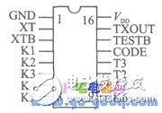
The key input of BA5048 is composed of 6-TImes; 3 matrix composed of Kl-K6 and Tl~T3. The key combination of K1~K6 and Tl outputs a continuous signal, and 63 kinds of key codes can be realized by adding a coding diode to T1 to K1~K6. The output characteristic of the continuity signal is that when a continuous button is pressed, the command transmits the signal twice, each period of the signal is 20.25 ms, the signals are separated by 33.8 ms, and then there is a pause of 87.8 ms. Then another cycle begins until the button is raised. The combination of K1~K6 and T2~T3 outputs a one-time trigger signal. Pressing the keyboard only once corresponds to one output. The output characteristic of the one-time trigger signal is that when there is a one-time trigger button press, the command only transmits the signal twice, each signal period is 20.25 ms, the two signals are separated by 33.8 ms, and then stop.
The transmit command per cycle of the signal is a series of 12-bit words, as shown in Figure 1-129. In the figure, C1~C3 are code bits, different types of decoders correspond to different codes; H, S1, S2 correspond to Tl, T2, T3, indicating continuous signal or one-time trigger signal; D1 ~ D6 correspond to K1 ~ K6 buttons A 6-digit information code.
The BA5050 continuously receives two sets of transmit signals when receiving a signal to determine if the signal is normal. First, the digital of the first group of signals is stored in the on-chip 12-bit conversion register; then, when the second group of signal codes is received, it is immediately compared with the number in the conversion register to see if it is the same: if different, the system immediately It is reset; otherwise, when all received codes are normal, the respective outputs rise from low level to high level.
To prevent interference from other models, the BA5050 provides two code bits, CODE1 and CODE2, to check if the transmitter and receiver codes are identical. Only when the two codes are identical, the following data bits are valid to produce the corresponding output; otherwise, no output is generated.
The single pulse output pins SP1 to SP10 output a positive pulse having a width of 107 ms immediately after receiving two sets of signals continuously. As long as the continuous pulse output pins HP1 to HP6 receive a valid continuous signal, the corresponding output remains high. When the continuous signal of the release button is terminated, the output goes low for about 160 ms. HP1 to HP6 can output high levels in parallel at the same time. Reverse level output pins CP1 and CP2, each time a valid signal is received, the output level is reversed.
The BA5050 is extremely resistant to interference from televisions, fluorescent lamps, and energy-saving lamps.
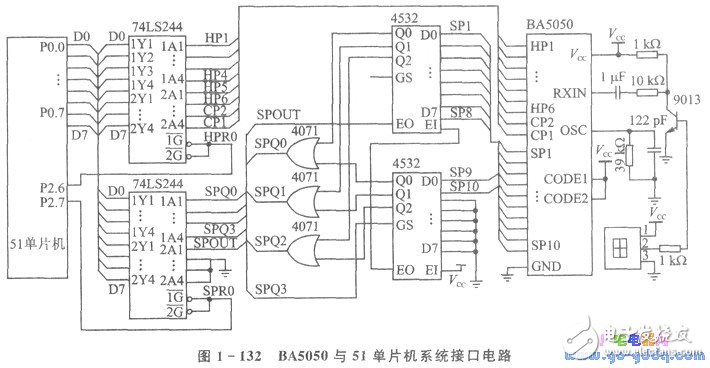
Figure 1-132 shows the interface circuit between the BA5050 and 51 microcontroller systems. The circuit uses two ports to process the received key code data. The HPRO port is used to read continuous button signals (HP1 to HP6) and reverse button signals (CP1 and CP2). HP1 to HP6 can be combined in 63 combinations, and the range of key codes is OIH to 3FH. In the actual application system, the HP1 to HP6 arrangement combination buttons are generally set to various function buttons, and the CP1 and CP2 are set to be similar to the functions of the power switch and the mute. The SPRO port is used to read the one-shot button signals (SP1 to SP10). The SP1~SP10 signals are added to the port through the decimal encoding circuit. Therefore, when no SP key is pressed, the data read by this port is 10H; when the SP key is pressed, the corresponding key codes of SP1~SP10 are OOH~09H. It has been converted into OIH~OAH in the following subroutine. In practical applications, it is generally associated with 1~9 and 0 ten numeric keys.
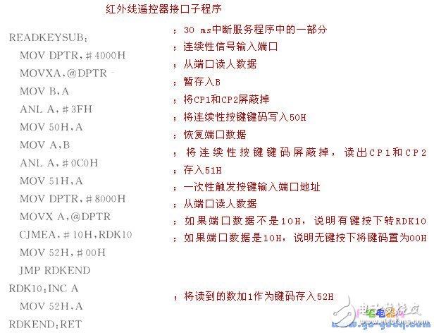
The following is a subroutine for reading the remote control key code: 50H for the continuity key code value; 51H for the reverse level output CP1 and CP2 status; 52H for the one-time trigger key code. Readers can define the function of the button and the processing of the key code according to the values ​​of 50H, 51H, 52H and the specific application system. The basic structure of the program is to determine the key value and then perform the corresponding jump processing.
Air Conditioner Controller PCBA
Controller Pcb Board ,Pcba Assembly,Pcba Controller Board,Conditioner Controller Pcba
Full Industrial CO.,ltd. , https://www.iotaindustrial.com