The SPI bus system is a synchronous serial peripheral interface; it is a high-speed, full-duplex, synchronous communication bus, and occupies only four wires on the pins of the chip, saving the pins of the chip, and at the same time Space saving and convenience in the layout of the PCB is precisely because of this simple and easy to use feature, and now more and more chips integrate this communication protocol. Many chips communicate with this protocol: EEPROM, Flash, real-time clock, AD converter, digital signal processor, etc.: The USART module of MSP430 can not only implement asynchronous mode (see: MSP430 library "two" UART asynchronous serial port), It also supports synchronous serial communication (ie SPI mode); its SPI supports 3-wire, 4-wire operation, supports host mode and slave mode, and the character length can be 7 or 8 bits. Because the AD7708 chip is used to complete AD sampling, the AD7708 communicates with other devices through the SPI; this program is simplified, and only the host mode is initialized.
Hardware introduction:
SPI: SPI is Motorola's first definition on its MC68HCXX series processor. It is a synchronous high-speed serial communication protocol. For details on the SPI protocol, refer to: SPI_Interactive Encyclopedia.
MSP430 support for SPI: When the bit SYNC of the msp430USART module controller UxCTL is set, the USART module works in synchronous mode. For 149, it works in SPI mode. If it is 169, USART0 can support I2C and can be controlled by another control bit I2C. The I2C bit 0 works on the SPI. In SPI mode, the microcontroller is allowed to transmit and receive 7-bit or 8-bit data at a determined rate.
Synchronous communication is similar to asynchronous communication; synchronous communication and asynchronous communication register resources are consistent, and the functions between different bits of a specific register are different; for the contents of specific registers, refer to the user guide provided by TI.
The SPI operation of the USART module can be 3-wire and 4-wire, and the signals are as follows:
SIMO: From the main to the main, in the host mode, data output; slave mode, data input.
SOMI: from the master, host mode, data input; slave mode, data output.
UCLK: USART SPI mode clock, the signal has a master output, slave input.
STE: Slave mode sends and receives the enable control pin for 4-wire mode, controlling multiple slaves in the multi-master slave system to avoid collisions. The specific method is as follows (the figure is taken from the user guide):
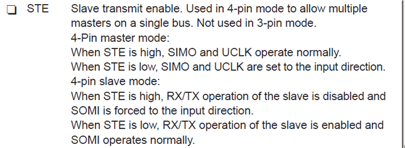
Four-wire master mode: STE is high, SIMO and UCLK are normal; STE is low, SIMO and UCLK are set to input direction, and host control is given out.
Four-wire slave mode: STE is high, the slave's transmit and receive are invalid, and SOMI is set to the input direction; STE is low, transmit and receive are normal, and SOMI is also normal output.
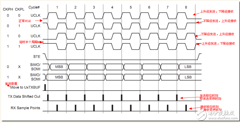
USART module serial clock polarity and phase settings:
The polarity and phase of the USART clock UCLK are controlled by the CKPH and CKPL bits located in the UxTCTL register, as shown in the following figure: In the program, I call it, clock mode 0, clock mode 1, clock mode 2, clock mode 3.
The USART baud rate is generated, SPI is different from asynchronous communication: asynchronous communication is controlled by UxBR1\UxBR0\UxMCTL three registers to generate standard frequency; while in synchronous mode, the master and slave devices use the same clock, no longer need to generate standard clock. Therefore, the UxMCTL register is no longer used, and its value is 0.
Others are basically the same as asynchronous communication, and will not be elaborated here. Refer to the user guide for details.
Program implementation:
The program is similar to the asynchronous communication: the first is to initialize the function, then the data is read and the data function is written. This program uses a structure similar to my previous UART library. After writing data, it enters a low-power wait interrupt, and judges the flag bit to write data and read data.
Here the function only implements the 430 host mode. If you want the slave mode, you can follow the example of my program and simplify the implementation.
Because the SPI device (AD7708) I am going to use is not a character device, the write string function is no longer implemented here, and the printf and scanf functions are not migrated. If you need to add it yourself, the printf and scanf migration reference: MSP430 program Library "four" printf and scanf function transplantation
Initialization function: SpiMasterInit, to achieve the initialization of the host mode, the function content is as follows:
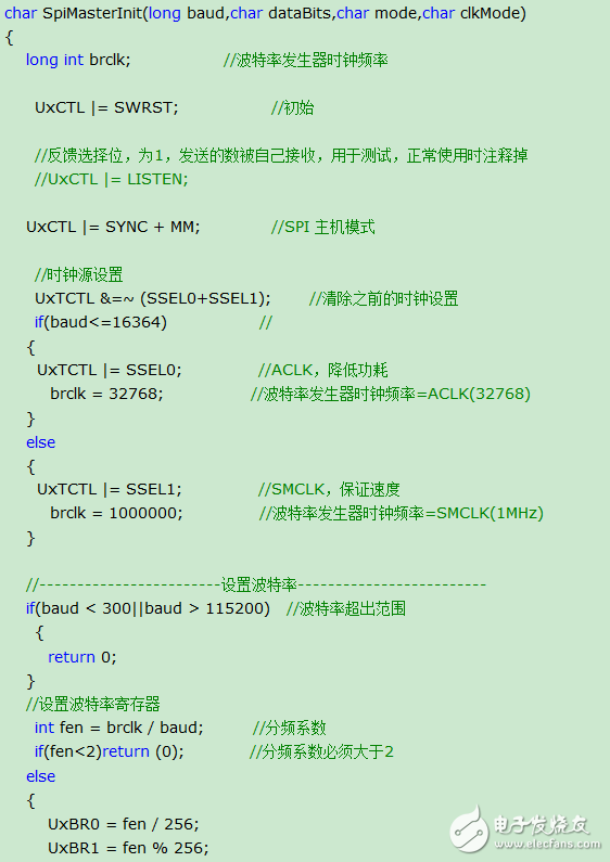
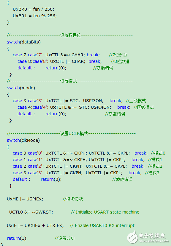
The program comments have been detailed, so I won't go into details here; if you want to change to the slave mode, you should remove the clock settings and baud rate settings.
Send function and receive function:

The send and receive functions are almost the same as in asynchronous communication. If the flag is 0, then wait for a change to 1, then write or read; the flag is changed in the interrupt function; the interrupt function is as follows:
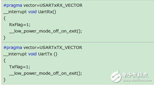
After the interrupt is set to only the flag bit, the low power consumption is exited; after exiting, the data is written or read.
Read or write the SpiLpm function of the function call:
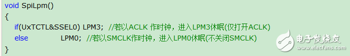
According to different situations, enter low power consumption. If the microcontroller does not allow low power consumption elsewhere, you can change this function.
The program part is so much more. The required function is declared in the header file for ease of use.
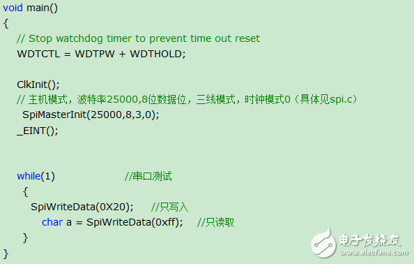
Example of use:
The program is used in the same way as the previous library. Add the c file, including the h file. After calling the initialization function, you can use the function in the library.
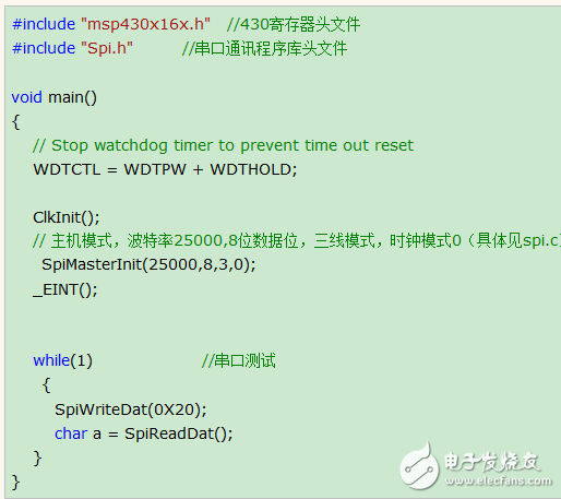
Here is just a simple use example, the detailed use, will be given in the next article, the next one: MSP430 library "six" through the SPI operation AD7708; will use today's library to complete the communication part of the SPI.
Precautions:
SPI is full-duplex communication. Each time the 8-bit/7-bit data is written (transmitted), the SPI master module of 430 reads the sampled 0/1 signal half a clock cycle after transmission and stores it in the receive buffer register. So, every time you write, there is data to read, but it is not necessarily sent back from the device. This place must be noted when using 430 host mode, it is easy to make mistakes (I also pay attention when debugging AD7708) To this place); SPI function has added SpiWriteData function, this function will return the received data after half a clock cycle after sending, convenient to use; it is not recommended to use the previous send and read functions, very It is easy to make mistakes; it is recommended to use this function just added, the library has been updated and can be downloaded again. Function SpiWriteData:
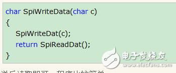
Read after sending, the program is relatively simple.
New sample program:
Direct Welded Plastic Shell Integrator
Direct Welded Plastic Shell Integrator,Micro Module Integrator,Potting Module Integrator,Direct Welded Modular Integrator
Zibo Tongyue Electronics Co., Ltd , https://www.tongyueelectron.com