1 Introduction
With the development of communication technology, the number and types of optical modules and devices are increasing, making the electromagnetic environment increasingly complex and electromagnetic pollution becoming more and more serious. In this complex electromagnetic environment, how to reduce the electromagnetic disturbance between various electronic devices, improve the electromagnetic compatibility of optical modules, and enable various devices to coexist and work properly has become a key in the design of electronic products. content.
The purpose of EMC (Electromagne TIc CompaTIbility) design is: an electronic device or system can work normally in the expected electromagnetic environment, without performance degradation or failure; at the same time, the electromagnetic environment is not a source of pollution. In order to achieve electromagnetic compatibility, we must first analyze the factors that form electromagnetic interference, in order to find a solution to the problem.
The formation of electromagnetic interference must have the following three factors:
1 Electromagnetic disturbance source refers to a component, device, device, subsystem, system or natural phenomenon that produces electromagnetic disturbance.
2 Coupling pathway, or coupling channel, refers to a pathway or medium that couples (or transmits) energy from a source of disturbance to a sensitive device.
3 Sensitive equipment, refers to equipment that responds to electromagnetic disturbances.
In view of the above three factors, there are many ways to suppress the influence of electromagnetic interference. From the perspective of optical module structure design, the electromagnetic shielding method is used to cut off the coupling path of electromagnetic disturbance, which is the key to improve its electromagnetic compatibility performance. One of the effective technical means.
2 Electromagnetic shielding structure analysis
2.1 Shielding effectiveness
Electromagnetic shielding is the separation of metal between two spatial regions to control the induction and radiation of electric, magnetic and electromagnetic waves from one region to another. Specifically, the shield is used to surround the components, circuits, assemblies, cables, or the entire system of disturbance sources to prevent the electromagnetic field from spreading outward; the shields are used to surround the receiving circuits, devices, or systems to prevent them from being exposed to the outside world. The influence of electromagnetic fields. Because the shield acts on absorbing electromagnetic energy, reflecting energy, and canceling energy from external electromagnetic waves and internal electromagnetic waves from wires, cables, components, circuits, or systems, the shield has the function of reducing disturbance.
The ability of the shield to suppress radiated disturbances is expressed by the electric field shielding effectiveness SE or the magnetic field shielding effectiveness SH:
SE=20lg(E1/E2)(dB)
SH=20lg(H1/H2)(dB)
In the formula, E1 and H1 are respectively the electric field strength and the magnetic field strength measured when unshielded; E2 and H2 are respectively the electric field strength and magnetic field strength measured after shielding.
2.2 shielding materials
To determine what material should be used to make the shield, you need to know what the shielding effectiveness of the material is and what parameters of the material. According to the shielding mechanism, the shielding can be divided into three categories: electric field shielding, magnetic field shielding and electromagnetic field shielding.
The electric field shielding is to reduce the coupling voltage of the disturbing electric field to the sensitive circuit, and to provide a conductive metal shield between the disturbance source and the sensitive circuit, and ground the metal shield. As long as the metal shield is managed to be well grounded, the coupling voltage of the disturbing electric field to the sensitive circuit can be made small. The electric field shield is mainly reflective, so the thickness of the shield does not have to be too large, and a thin layer of shielding or a thin conductive layer on the plastic can be used.
Magnetic field shielding has low frequency and high frequency. Low-frequency magnetic field shielding uses a material with high magnetic permeability to form a low reluctance path, so that most of the magnetic field is concentrated in the shielding body. Therefore, the higher the magnetic permeability of the shield, the larger the thickness, and the smaller the magnetic resistance, the better the effect of the magnetic field shielding. When the magnetic field frequency is high, the magnetic permeability of the high magnetic permeability material decreases, and the magnetic loss increases. Instead, the reverse magnetic field of the eddy current generated by the high conductivity material should be used to cancel the disturbance magnetic field to achieve shielding. The shield used to shield the magnetic field does not need to be grounded.
Electromagnetic field shielding generally uses a material with high conductivity as a shield and grounds the shield. It uses the reverse magnetic field of the eddy current generated by the high conductivity material to counteract the disturbing magnetic field, and the electric field shielding is realized by the grounding of the shielding body. Since the wavelength becomes close to the size of the hole on the shield as the frequency increases, the key to the electromagnetic field shielding is to control the leakage of the hole of the shield in addition to the high conductivity material.
The electrical conductivity and magnetic permeability of the shielding material are measured by relative conductivity σr and relative magnetic permeability μr, respectively. Table 1 lists the σr and μr values ​​of commonly used shielding materials [1].
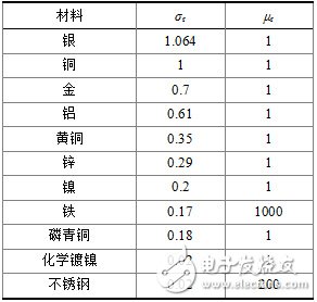
It can be seen that in order to improve the shielding performance, the high conductivity material can be aluminum, copper, or aluminum copper plating. When the requirement is higher, silver can be further plated. The high magnetic permeability material may be stainless steel or iron, and the thickness of the material may be appropriately increased.
2.3 Shield design
There are two factors that affect the shielding effectiveness of the shield: first, the shield must be intact and the surface can be continuously conductive; second, there must be no conductors that directly penetrate the shield to prevent antenna effects. However, in practical applications, the shielding body often has a heat dissipation hole, or the shielding body itself is composed of several parts, and there is an assembly gap.
Whether the gap or hole leaks electromagnetic waves depends on the size of the gap or hole relative to the wavelength of the electromagnetic wave. When the wavelength is much larger than the hole size, no significant leakage occurs; when the hole size is equal to an integral multiple of half a wavelength, the electromagnetic leakage is the largest. Generally, the hole size is required to be less than 1/10 to 1/2 of the shortest wavelength. Therefore, when the frequency of harassment is high, the wavelength is short and attention must be paid to this problem.
For assembled shields, there are several ways to improve shielding effectiveness:
1 The contact surface should be as flat as possible to reduce the contact resistance.
2 Add an elastic conductive material to the contact surface to prevent leakage of electromagnetic waves. Such as conductive foam or metal reed pad.
3 Assembled by screws, the spacing of the mounting screws can be reduced to reduce the length of the gap.
4 Make the contact surface into a single or double stop assembly to increase the tightness of the shield, as shown in Figure 1.
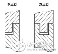
Figure 1 Schematic diagram of the stop structure
For the design of the vents, several small round holes can be used instead of one large hole, and the spacing between the vents is guaranteed to be greater than 1/2 wavelength. as shown in picture 2.
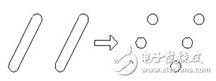
Figure 2 Schematic diagram of ventilation holes
3 test results and analysis
Taking the company's products as the test platform, the above method was used to optimize the XFP module shell structure design, and the module samples were made, and the samples were tested. The sample structure is shown in Figure 3.

Figure 3 XFP module outline drawing
According to FCC 47 CFR Part 15 Subpart B secTIon 15.109(a), the peak value of the electromagnetic disturbance field strength is 74 dBμV/m and the average limit is 54 dBμV/m.
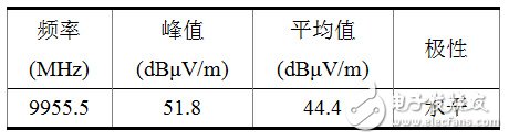
The test results of the electromagnetic interference field strength of the XFP module before the improvement in the horizontal direction are shown in Figure 4 and Table 2:
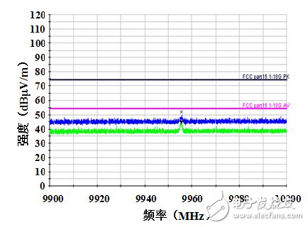
Figure 4 Improve the front horizontal direction test chart
Table 2 Improve the front horizontal direction test data
The test results of the electromagnetic interference field strength of the XFP module before the improvement in the vertical direction are shown in Figure 5 and Table 3:
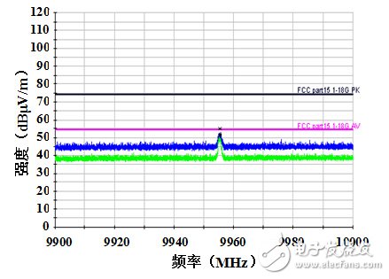
Figure 5 Improve the front vertical direction test chart
Table 3 Improve the front vertical direction test data

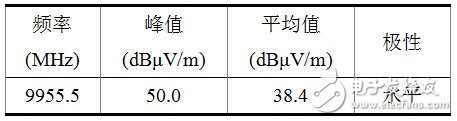
The improved XFP module electromagnetic disturbance field strength in the horizontal direction test results are shown in Figure 6 and Table 4:
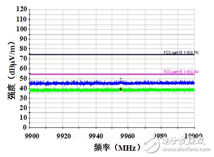
Figure 6 Improved horizontal direction test chart
Table 4 Improved horizontal direction test data
The improved XFP module electromagnetic disturbance field strength test results in the vertical direction are shown in Figure 7 and Table 5:
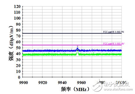
Figure 7 Improved vertical direction test chart
Table 5 Improved vertical direction test data
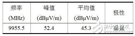
It can be seen from the above test data that the maximum peak value of the improved electromagnetic disturbance field strength decreased by nearly 2 dBμV/m, and the average value decreased by nearly 6 dBμV/m.
4 Conclusion
In the structural design of the optical transceiver module, the electromagnetic shielding design must be considered as the key consideration. When the shielding design is specifically developed, the characteristics of the disturbance source should be determined first, then the appropriate shielding material should be selected, and then the appropriate shielding method should be combined to achieve the best shielding effect. The test results of the samples show that the electromagnetic compatibility of the module has been greatly improved, and the performance indicators of the module have not been affected.
ul 30, 2021 (AmericaNewsHour) -- In a recent published report, Kenneth Research has updated the market report for Lithium Iron Phosphate (LiFePO4) Battery Market for 2021 till 2030. Report further now discusses; the various strategies to be adopted or being adopted by the business players across the globe at various levels in the value chain. In the view of the global economic slowdown, we further estimated that China, India, Japan and South Korea to recover fastest amongst all the countries in the Asian market. Germany, France, Italy, Spain to take the worst hit and this hit is expected to be regain 25% by the end of 2021- Positive Growth in the economic demand and supply.
U.S. Market recovers fast; In a release on May 4th 2021, the U.S. Bureau and Economic Analsysis and U.S. Census Bureau mentions the recovery in the U.S. International trade in March 2021. Exports in the country reached $200 billion, up by $12.4 billion in Feb 2021. Following the continuous incremental trend, imports tallied at $274.5 billion, picked up by $16.4 billion in Feb 2021. However, as COVID19 still haunts the economies across the globe, year-over-year (y-o-y) avergae exports in the U.S. declined by $7.0 billion from March 2020 till March 2021 whilest imports increased by $20.7 billion during the same time. This definitely shows how the market is trying to recover back and this will have a direct impact on the Healthcare/ICT/Chemical industries, creating a huge demand for Lithium Iron Phosphate (LiFePO4) Battery Market products.
Portable Energy Storage System,Portable Energy Storage Market,Portable Power Storage,Portable Energy Storage
Shenzhen Zhifu New Energy Co., Ltd. , https://www.sunbeambattery.com