The following provides a reference design for automotive LED systems. Use the MAX15005 to boost an 8V to 16V automotive battery to 21V to drive a string of 6 to 8 LEDs.
The key parameters of the reference design are listed below, and the required detailed circuit schematic (Figure 1) and bill of materials (Table 1) are given.
Specifications VIN: 8V to 16V (continuous), 40V (transient) VLED + supply voltage: 21V ± 5% at 80mA (maximum) VLED + load range: 10V to 20V at 70mA ILED: 70mA ± 5% brightness adjustment input: 400Hz, 50Ω , Open collector brightness adjustment resolution: 3µs Switching frequency: 385kHz Operating temperature: -40 ° C to + 125 ° C
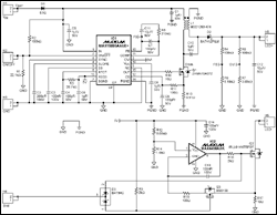
Detailed drawing (PDF, 92kB)
Figure 1. MAX15005 reference design
Table 1. List of materials
| Designator | Value | DescripTIon | Part | Footprint | Manufacturer | QuanTIty |
| C1, C5, C6, C8, C10 | 1µF / 50V | Capacitors | GCM31MR71H105KA55L | 1206 | Murata | 5 |
| C2 | 200pF / 100V | Capacitor | GRM2165C2A201JA01D | 0805 | Murata | 1 |
| C3, C13, C14 | 100nF / 100V | Capacitors | GCM21BR72A104KA37L | 0805 | Murata | 3 |
| C4, C7, C9 | 100pF / 50V | Capacitors | GRM2165C1H101JA01D | 0805 | Murata | 3 |
| C11 | 10nF / 50V | Capacitor | GRM216R71H103KA01D | 0805 | Murata | 1 |
| C12 | 10µF / 50V | Capacitor | UUD1H100MCL1GS | SMD | Nichicon | 1 |
| D1 | 1A / 400V | Diode | S1G | SMA | Fairchild | 1 |
| D2 | 200mA / 100V | Schottky diode | BAT41ZFILM | SOD123 | STM | 1 |
| D3 | 200mA / 30V | Schottky diode | STM | SOT23 | STM | 1 |
| L1 | 470µF / 0.86A | Inductor | MSD1260-474 | SMD | Coilcraft | 1 |
| Q1 | 1A / 100V | n-FET | ZXMN10A07Z | SOT89 | Zetex | 1 |
| Q2 | 2A / 55V | n-FET | IRLL014NTRPBF | SOT223 | InternaTIonal RecTIfier | 1 |
| Q3 | 220mA / 50V | n-FET | BSS138 | SOT23 | Fairchild | 1 |
| R1 | 22.1kΩ | Resistor | SMD, 1%, 0.125W | 0805 | Vishay | 1 |
| R2, R4, R6 | 100kΩ | Resistors | SMD, 1%, 0.125W | 0805 | Vishay | 3 |
| R3 | 26.7kΩ | Resistor | SMD, 1%, 0.125W | 0805 | Vishay | 1 |
| R5 | 6.19kΩ | Resistor | SMD, 1%, 0.125W | 0805 | Vishay | 1 |
| R7 | 3.65kΩ | Resistor | SMD, 1%, 0.125W | 0805 | Vishay | 1 |
| R8 | 210kΩ | Resistor | SMD, 1%, 0.125W | 0805 | Vishay | 1 |
| R9, R16 | 2kΩ | Resistors | SMD, 1%, 0.125W | 0805 | Vishay | 2 |
| R10 | 10Ω | Resistor | SMD, 1%, 0.125W | 0805 | Vishay | 1 |
| R11 | 100Ω | Resistor | SMD, 1%, 0.125W | 0805 | Vishay | 1 |
| R12 | 8.66kΩ | Resistor | SMD, 1%, 0.125W | 0805 | Vishay | 1 |
| R13 | 0.51Ω | Resistor | Sense resistor | SL1 | Vishay | 1 |
| R14 | 1.4kΩ | Resistor | SMD, 1%, 0.125W | 0805 | Vishay | 1 |
| R15 | 100Ω | Resistor | SMD, 1%, 0.125W | 0805 | Vishay | 1 |
| R17 | 10Ω | Resistor | SMD, 1%, 0.205W | 1206 | Vishay | 1 |
| IC1 | MAX15005A | Boost controller | MAX15005AAUE + | 16-TSSOP-EP | Maxim | 1 |
| IC2 | MAX4400 | Single op-amp | MAX4400AXK + | 5-SC70 | Maxim | 1 |
The oscilloscope screenshots in Figures 2, 3, and 4 show the switching waveforms at three different dimming inputs.
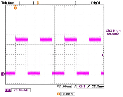
Figure 2. ILED waveform measurement with VIN = 14V and 50.0% dimming ratio
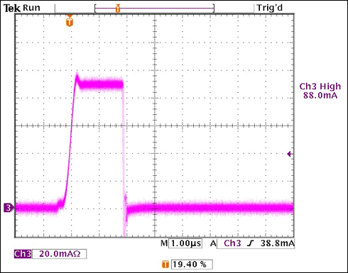
Figure 3. ILED waveform measurement with VIN = 14V and 0.1% dimming ratio
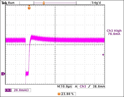
Figure 4. ILED waveform measurement with VIN = 14V and 99.9% dimming ratio
The Internet of Things (IoT) is the network of physical devices, vehicles, batteries, home Appliances, and other items embedded with electronics, software, sensors, actuators, and connectivity which enables these things to connect and exchange data, creating opportunities for more direct integration of the physical world into computer-based systems, resulting in efficiency improvements, economic benefits, and reduced human exertions.
Our Battery Remote Monitor with IoT is direct integration of the battery restore solution and device into computer-based battery monitoring system which combines wireless communication with patented, field-proven battery monitor and analysis technology. It not only has the ability to restore battery, but also has the ability to monitor battery's State-Of-Health(SOH) in real time.
Uptime is the most basic requirements in nowadays connected to all things in the world. Power systems rely on batteries to provide critical backup energy and power in sudden affairs. When power supply of normal grid is lost suddenly, the backup power systems must perform. Without proper monitoring of the back up power system status whether safe or not, there is a irreparable risk of catastrophic loss for Hospital institution, Telecommunication cost, financial organizations and even the army suddenly lost the war, etc.
How our Battery Remote Monitor IOT works? it is comprised of 3 base hardware devices and 1 software operation system. The monitor parts connected with batteries pack and reliably reports battery State-Of-Health(SOH) to the software platform. Wirelessly enables these monitoring hardware to connect and exchange data with users in working to control the batteries status in real time.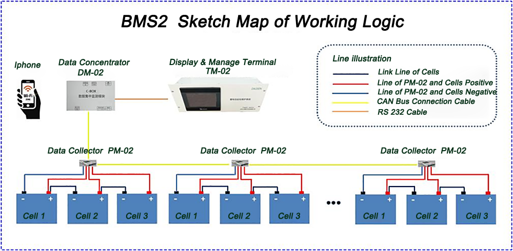
Our family members of Battery Remote Monitor IoT are Battery Smart Pulse Protector with BlueTooth and GPS tracking management such as Car or Truck GPS System , Telecom Base Site Battery Protector System with wireless monitor, Battery Smart Remote Monitoring system and Battery Anti-Theft GPS System, etc.
Battery Remote Monitor IOT
Battery Remote Monitor IOT,Battery Remote Monitor IOT,Battery Remote Monitoring,Home Battery Remote Monitoring,Monnit Temperature Sensor
Shenzhen Daceen Technology Co., Ltd. , https://www.daceen-sz.com