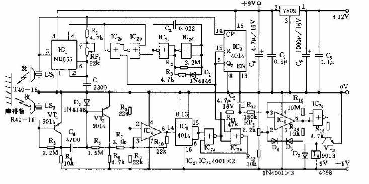
As shown, the collision avoidance device includes an ultrasonic pulse transmitting circuit and an ultrasonic receiving circuit with a detection distance of 5 meters.
IC2 adopts four 2 input terminal or non-gate CD4001, among which 1C2c and IC2d constitute a low frequency pulse generator. IC2c and IC2b form a bistable circuit. The output of IC2c is applied to the reset terminal 4 of 1C1 (555), which causes 555 to be in a forced reset state during a steady low period. IC1 and R1, RP1, Cl form an astable multivibrator. When the IC2c is output at high level, it starts to oscillate. The oscillation frequency is f=1.44/(Rl ten RP1)Cl, and the frequency corresponding to the graphic parameter is 25~150kHz. Adjust RP1 to make the oscillation at 40kHz. The output of IC1 is added to the CP terminal of the counting circuit IC3 (14-pin). IC3 uses a decimal counter/pulse splitter, and its Q7 (6-pin) is connected to the reset terminal R (15-pin). A ring counting circuit is formed, and when the Q7 of the counting circuit is output to the bistable circuit 1C2c, the counting circuit is cleared. That is to say, due to the control of the bistable circuit by the ring counting circuit, after a set of pulses of 7 cycles, the narrow pulse (high electron) of the Q7 output resets the bistable IC2, and outputs a low-level pulse. Force 555 reset, stop the oscillation, achieve pulse modulation of 40kHz. The 40 kHz modulated pulse from IC1 is radiated forward through the T40-16 ultrasonic head.
Wuxi Lerin New Energy Technology Co.,Ltd. , https://www.lerin-tech.com