In some places where high voltage and low current are required, a voltage doubler rectifier circuit is often used. Double voltage rectification can lower the AC voltage and use a high-voltage rectifier diode and capacitor to “finish†a higher DC voltage. The voltage doubler rectifier circuit is generally divided into two voltage, three voltage and multiple voltage rectifier circuits according to how many times the output voltage is the input voltage.
The working principle of double voltage rectifier circuit:Double voltage rectification circuit: Using the storage function of the filter capacitor, the output voltage of several times the voltage of the secondary side of the transformer can be obtained by a plurality of capacitors and diodes, which is called a voltage doubler rectifier circuit. The circuit is shown below.
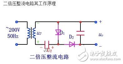
★ When u2 is in the positive half cycle, the voltage polarity is as shown in the figure, D1 is on and D2 is off; C1 is charged, the current direction and the voltage polarity on C1 are as shown in the figure, and the maximum voltage of C1 is reachable.
★ When u2 is negative for half a week, the voltage polarity is as shown in the figure, D2 is turned on, D1 is turned off; C2 is charged, the current direction and the voltage polarity on C2 are as shown in the figure, and the maximum value of C2 voltage is reachable.
It can be seen that the storage of the charge causes the output voltage (ie, the voltage on C2) to be twice the voltage of the secondary side of the transformer, and the same principle can be used to achieve the desired multiple of the output voltage.
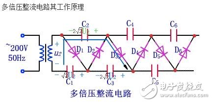
As shown in the above figure, the multi-voltage rectifier circuit is obtained. According to the above analysis method, the voltage on C1 is the voltage on C2 to C6. Therefore, the value of the output voltage is taken as the output end of C1; the value of the output voltage is taken as the output end of C2; the voltage is added as the output on C1 and C3, and the value of the output voltage is... This type of push, output from different positions, can get 4, 5, 6 times the output voltage.
Advantages and disadvantages of the voltage doubler rectifier circuit:The essence of the voltage doubler rectifier circuit is the charge pump. Initially, because nuclear technology required higher voltages to simulate artificial nuclear reactions, a high-voltage voltage doubler circuit was proposed by COCCROFT and WALTON in 1932, commonly referred to as a CW voltage doubler rectifier circuit.
The voltage doubler rectifier circuit has various structures, each having advantages and disadvantages. Common circuits are as follows:
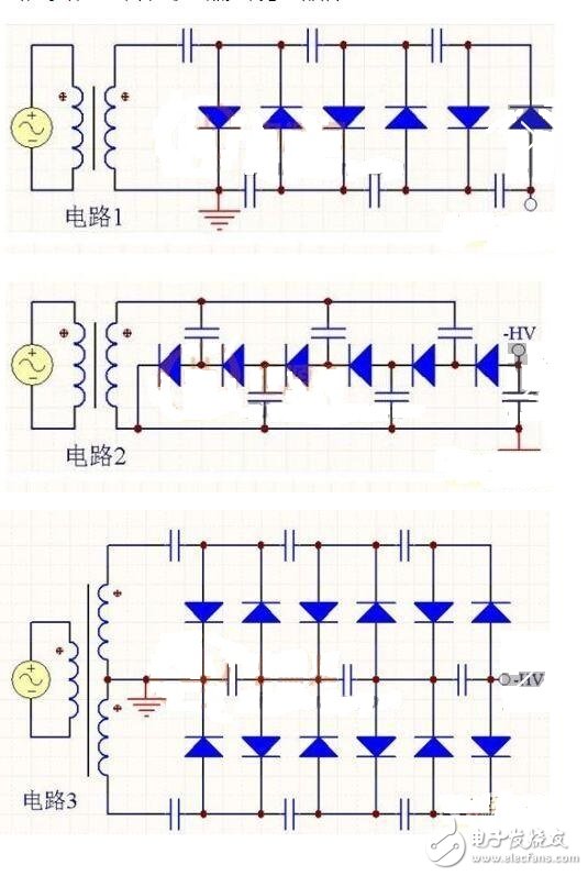
These three circuits are all 6 times voltage rectifier circuits, each with its own characteristics. We usually say that every 2 times is the first order, denoted by N, the above circuits are all 3 orders, that is, N=3. If you want the output voltage to be different in polarity, just reverse all the diodes.
The advantage of circuit 1 is that the voltage on each capacitor does not exceed twice the secondary peak voltage U of the transformer, ie 2U, so a capacitor with a lower withstand voltage can be selected. The disadvantage is that the capacitor is in series discharge and the ripple is large.
The advantage of the circuit 2 is that the ripple is small, and the disadvantage is that the voltage withstand voltage of the capacitor is high, and as the N increases, the voltage stress of the capacitor increases. The voltage of the last capacitor in the figure reaches 6U.
Circuit 3 is an improvement of circuit 1. The advantage is that the ripple is much smaller than circuit 1, and the voltage stress of the capacitor does not exceed 2U. The disadvantage is that the circuit is complicated.
The circuit 1 is taken as an example to illustrate the working principle:
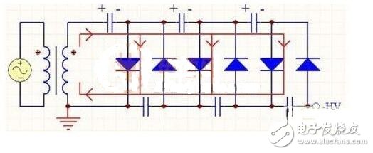
When the secondary output of the transformer is up and down, the current flows as shown. The transformer charges energy to the three capacitors of the upper arm.
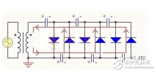
When the secondary output of the transformer is up-down, the current flows as shown. The upper arm capacitor is charged through the secondary arm of the transformer.
If there is no load, in steady state, except for the leftmost capacitor, the voltage on each of the other capacitors is 2U, so the total output voltage is 6U. In fact, due to the poor carrying capacity of the high-order voltage doubler rectifier circuit, the output of a small power will cause a large drop in the output voltage. Assuming that the output current is I, the capacity of each capacitor is the same, C, and the AC power frequency is f, then the voltage drops to:
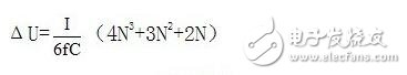
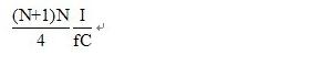
The output voltage ripple is:
M12 Circular Connectors,M12 P Nylon Adhesive Waterproof Connector,M12 Industrial Waterproof Connector,M12 8-Core Male Head Waterproof Connector
Shenzhen HuaTao Electronic Co., LTD , https://www.htconnector.com