With the development of embedded and communication technologies, CNC systems have experienced the development process from the traditional single-processor centralized architecture to the open architecture to the multi-processor distributed CNC system architecture. The distributed CNC system takes the high-precision and high-speed processing features as the core of development, and at the same time achieves the development of a new generation of manufacturing systems with high real-time, high reliability and high compatibility by seamlessly integrating information between heterogeneous networks. .
In order to improve the real-time communication ability of distributed CNC system, Tao Lin et al [1] proposed a real-time communication network based on Ethernet distributed CNC system; Song Zhenjun et al [2] proposed distributed control based on industrial Ethernet System architecture, although Ethernet technology has good stability, low cost, high bandwidth and excellent compatibility, Ethernet CSMA / CD (carrier multiple access, collision detection) transmission mechanism determines that it can not Ensuring network transmission delays, resulting in poor real-time performance. Jin Zhenhua [3] proposed a distributed CNC system based on CAN bus. Although various field buses are widely used to connect field devices, they have the advantages of simple wiring, low hardware cost, accurate operation and stability, but the data transmission rate is low and the real-time performance is not. high. Reflective memory network fiber bus not only has a higher data transmission rate than Ethernet and field bus, but also is a real-time, deterministic network, which can better solve the real-time problem of data transmission in real-time systems [4-5].
Reflective memory technology is used in all applications where Ethernet or Fibre Channel or other serial networks are used to connect computers or programmable logic controllers, such as real-time flight simulators, telecommunications, high-speed process control (rolling mills and aluminum manufacturing) Factory), high-speed test and measurement systems, etc., but not for all applications [6 - 8]. Therefore, whether the reflective memory network is suitable
In the distributed numerical control system, how to effectively apply the reflective memory network to the numerical control machine tool becomes a key problem in the application of the reflective memory network. Based on the analysis of the basic structure of distributed numerical control system and the working principle of reflective memory network, this paper proposes a real-time communication network scheme of distributed numerical control system based on reflective memory network, and gives the basic frame structure, node model and expansion of the system. structure. The realization of the structural scheme not only greatly improves the network bandwidth, but also improves the real-time performance of the numerical control system data transmission.
1 Distributed CNC system basic structureThe distributed numerical control system is a comprehensive application of distributed control ideas on the numerical control system. With the increase of the function of the numerical control system and the improvement of the machining speed of the numerical control machine, many numerical control systems adopt a multi-microprocessor structure. Each microprocessor is connected through a data bus or communication mode, sharing the common memory and I/O interface of the system. Each processor shares part of the system [3, 9-11]. In distributed CNC systems, signal transmission is increasingly demanding real-time performance.
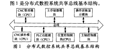
Figure 1 shows the basic structure of a shared CNC shared bus.
2 reflective memory network technology2. 1 Reflex memory network works
ReflecTIve Memory Network (RNN) is a high-speed real-time network. It is a high-speed shared memory network connected by fiber. Just like the general TCP/IP-based LAN, it also attaches a network card to each node computer. The reflective memory network interface adapter is an interface connecting each task device and the reflective memory optical network, and has the dual functions of data transmission and network management, and is the core device of the entire reflective memory ring network. The RM interface adapter is mainly composed of photoelectric conversion, data encoding/decoding/parallel processing, network management state machine, memory, protocol management module and task device interface. The system function block diagram is shown in Figure 2.
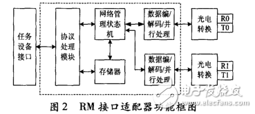
Figure 2 RM interface adapter functional block diagram
The reflective memory network is a special shared memory system. Each node occupies a corresponding memory address, and the entire system memory can be saved independently in each node subsystem. A reflective memory card is inserted into each node of the real-time communication network, and the card has dual-port memory, and each layer of software can read and write these memories [12 - 13]. Reflective memory networks enable memory-to-memory communication in distributed systems. After the data is written into the memory of the reflective memory card of one machine, the reflective memory card FPGA hardware automatically transmits the data through the optical fiber to the memory of the reflective memory network node card in the other reflective memory network of the real-time communication network. Usually, the update of a node is less than 0. With a time delay of 4 μs, the transmission traverses all the reflected memory cards, and the corresponding addresses in all the reflective memory network nodes are written to the corresponding data. Therefore, when accessing data, members of the real-time communication network can access the memory of the local reflective memory card [9, 14 - 15]. A reflective memory network node consists of local memory, an embedded interface, and arbitration logic to provide access to the host and reflected memory. The reflective memory network nodes can be installed or connected to different types of computer buses, including VME, PCI / PCI - X. , PCI Express, etc. [4].
2. 2 Reflective memory network topology
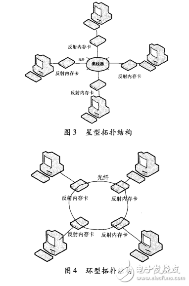
The reflective memory network is mainly composed of reflective memory cards connected by transmission media such as optical fibers. It mainly has two physical topologies: a star topology (as shown in Figure 3) and a ring topology (as shown in Figure 4). ). For a reflective memory network of a ring topology, adjacent reflective memory cards form a ring network through the connection of the input end and the output end, and the data packets are transmitted along the ring network. The advantage is that the fiber hub is not needed, the fiber usage is small, and the cost is saved; the disadvantage is that each node has a delay, and if any node or fiber fails, the data packet cannot be sent, resulting in the entire delivery network being paralyzed. Therefore, a star structure is generally employed. In fact, the star topology is just a physical structure because the internal structure of the hub is a ring connection. Logically, it is still a ring structure [4]. Each node in the network has a unique node ID. In the same network, two identical IDs are not allowed. This ID is set by the DIP switch on the board. The smaller the ID number, the higher the priority. When the data source node sends a packet through the hub, the hub can find the data transfer direction according to the high and low ID of the adjacent board, thereby updating the corresponding data of all nodes in real time. In a star configuration, if a node does not work, the hub can automatically shield the faulty node without affecting the data transmission of other nodes. Of course, the disadvantage of the star structure is that once the Hub in the network fails, the entire network will be 瘫痪 [ 16]. Figure 3 Star topology Figure 4 Ring topology
3 Construction of distributed numerical control system based on reflective memory network3. 1 CNC system network construction According to the characteristics of CNC system information transmission and overall transmission requirements, it is proposed to use reflective memory fiber bus to connect CNC device, PLC, fault diagnosis expert system, HMI control panel, CAD/CAM, CNC machining simulation system and other components. A distributed CNC system. Each task node of the bus network is connected to an RM (ReflecTIve Memory) interface adapter, and each RM interface adapter integrates a dedicated storage space, and the system maps the storage space to the address space of the network node processing system, so that the node processing system The operation of the RM interface adapter is the same as for the native memory. When the node task device writes data to a location mapped to the virtual address space of the reflective memory, the reflective memory network protocol propagates the data to every other node on the network in nanoseconds. And the updated propagation operation is asynchronous, without the intervention of the application system processor. The network connection structure of the CNC system is shown in Figure 5.
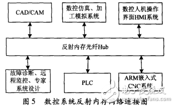
Fig. 5 Numerical control system reflection memory network connection diagram Distributed CNC system working process: CAD/CAM system models the machined parts and generates NC code according to the machining process [17]; NC simulation processing and machining simulation system carries out the generated NC code Graphic simulation, pre-processing to detect abnormal phenomena such as tool interference; HMI (Human Machine Operation Interface) as the input and display unit of the industrial computer is the medium for information exchange between the system and the user, showing the status of various control signals The operator can operate the machine tool through it, set and modify the machine parameters, and load the part processing file; the CNC module receives the processing code transmitted by the host computer, generates motion control commands through the interpreter and the interpolator; remote monitoring and The fault diagnosis expert system remotely monitors the running state of the machine tool by collecting the information of the numerical control system and the sensor body of the machine tool body, and analyzes the fault cause and locates the fault point for the operation fault. If these functions or systems are installed on a computer, the computer load will increase, and the interpolation process is a highly real-time process. These modules are connected by a reflective memory network, and there is almost no information exchange between them. The time delay is equivalent to a computer-implemented control, which can well meet the requirements of CNC machine tools for real-time processing.
3. 2 Reflective memory network communication process
Since the transmission of the reflective memory network is a pure hardware operation, it is not limited by a specific network protocol, and there is no need to write a complicated interface program. The software can perform read and write operations on the reflective memory card in only a few lines of code. The entire communication process is as follows: Step1: Open the board and reset the board; Step2: Board initialization settings: Execute the interrupt initialization function (INT_Init); Set the board interrupt packet interrupt enable (RM_IntDataArrive_IntEnable); Enable the fiber transceiver (RM_FM_Enable) Step3: Communication begins
(1) The sender sends an interrupt packet (RM_TxIntPkt). After the interrupt packet is interrupted, the interrupt handler automatically calls the interrupt handler (RM_Rx-IntPkt). The sender sends a data packet (RM_TxDatPk): When generating a write operation to the SDRAM, the reflective memory card automatically writes data and other related information (including data address, node number, etc.) into the transmit buffer, in the transmit buffer. The transmit circuit detects and converts the data into a 4- to 64-byte variable-length packet that is sent over the fiber interface to the receive port of the next board.
(2) The receiver receives the interrupt packet; after the interrupt packet is interrupted, the interrupt handler automatically calls the interrupt handler (RM_RxIntPkt). Receive the data packet (RM_RxDatPkt), write to the disk, open the thread function to query the board to receive the packet status (RM_IntStatus), first determine whether the node needs to write data, if not, directly forward the write interrupt to the next set of internal nodes. Otherwise, a read interrupt is sent after writing data to its reflected memory card, the receiving circuit unpacks the data packet and stores the data in the onboard receive buffer, in which another circuit writes the data to The local SDRAM is in the same address as the source node. At the same time, the circuit sends the data to the transmit FIFO, and the process is repeated until the transmitted data is returned to the source node receiving end, and then the source node deletes the same node ID data from the network, thereby realizing that all nodes are updated. Repeat the above process. Exit the program and close the board (RM_Card_close).
3. 3 Bandwidth and real-time analysis The interpolation period in high-speed and high-precision machining is generally controlled at 1 to 2 ms. The shorter the interpolation period, the closer the straight line segment of the straight line is to the actual machining curve, and the higher the machining accuracy. For the distributed numerical control system, the relatively independent geographical units are interconnected by the network communication system, and the bandwidth and real-time performance of the data transmission greatly affect the actual processing effect.
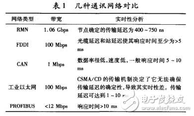
Table 1 compares the common network communication methods in several CNC systems. The transmit memory network bandwidth used in this paper can be up to 1. With 06Gbps and a network transmission delay of 400 to 750 ns, both of these specifications are significantly better than FDDI (Fiber Distributed - Data Interface), CAN, Industrial Ethernet and PROFIUBS fieldbus. Table 1 Several communication networks vs. network type bandwidth real-time analysis RMN 1. The transmission delay determined by the 06 Gbps node is 400 to 750 nsFDDI. The 100 Mbps cable delay and station delay have a response time of at least > 5ms. CAN 1 Mbps has a low data rate and low speed. The typical response time is 5 to 10ms. Industrial Ethernet 100 Mbps CSMA/CD The transmission mechanism determines that it cannot ensure the certainty of the transmission delay, resulting in poor real-time performance. Transmission delays up to 1 to 10 ms PROFIBUS < 12 Mbps response time > 10 ms4
End languageIn the field of reflective memory network technology applied to numerical control system, this paper has made a preliminary exploration. A real-time communication network scheme of distributed numerical control system based on reflective memory network is proposed. The basic framework structure of the system is given. Node model and extended structure. In practical applications, it is conceivable to combine the reflective memory network with Ethernet, use a reflective memory network in a strong real-time part, and use Ethernet in a weak real-time part to achieve full utilization of resources and reduce development costs.
Multi-core cpu is more and more popular, people are used to take dual core processors laptop before. However, Quad Core Laptop is becoming selling like a hot cake nowadays. You can find Quad Core Processor Laptop at our store, like I3 Quad Core Laptop,I7 Quad Core Laptop, I5 Quad Core Laptop, intel celeron J4125 or N5095 15.6 Inch Laptop, even N4120 quad core 14 Inch Laptop, etc. Therefore, you can just share the parameters prefer, like size, cpu, ram, rom, gpu, application scenarios, thus save much time to get a win-win solution.
Do you know the reason why more people choose quad core device? The core reason is that heavier tasks people need to finish at a higher speed than before. Nowadays quick rhythm is becoming the main style in city even everyone is eager to downshifting. So more powerful laptop, computer, mobile phone is a trend, though most functions never are used in lifetime.
15.6 inch Gaming Laptop or 14 Inch Gaming Laptop is becoming the most popular level at the market.
Quad Core Laptop,I3 Quad Core Laptop,I7 Quad Core Laptop,I5 Quad Core Laptop,Quad Core Processor Laptop
Henan Shuyi Electronics Co., Ltd. , https://www.sycustomelectronics.com