The research goal of this paper is to design H. The Exp-Golomb decoder in the 264 standard proposes an efficient and low-cost ASIC implementation scheme based on an in-depth discussion of its algorithm.
Exp-Golomb coding principle and decoding algorithm analysis
At H. In the 264 basic specification, except for the residual transformation coefficients using the CAVLC encoding method, all other syntax elements are encoded using Exp-Golomb. Exp-Golomb encoding is a regular variable-length encoding method, which is widely used in various video encoding standards. Exp-Golomb coding is based on the probability statistics of symbols. Short code words are used to indicate information with high probability of occurrence, and long code words are used to indicate information with low probability of occurrence. The code length has an exponential correspondence with the number to be encoded, so that the overall The average codeword is the shortest. Compared with fixed-length coding, it saves a lot of storage space.
At H. In 264, the 0th order Exp-Golomb coding is adopted. The coding rules are shown in Figure 1.
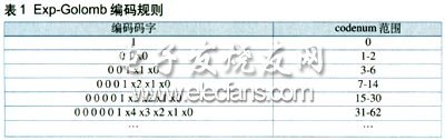
The logical structure of the Exp-Golomb codeword is: [M zeros] [1] [INFO]. Among them, M 0s and 1s in the middle are called prefixes, and INFO is the information value of M bits. Therefore, the length of each Exp-Golomb codeword is 2M + 1. Each index word codenum can correspond to a code word structured as above, and the relationship between them is:
codenum = 2M + INFO-1 (1)
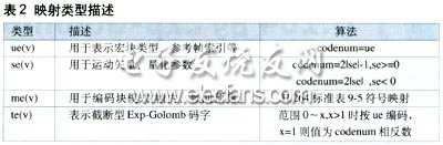
It can be seen from Equation 1, that by performing Exp-Golomb decoding, the number of consecutive Os before the codeword can be detected first, and then the suffix is ​​taken out, and the codenum value can be obtained by calculation by the formula. At H. There are four types of Exp-Golomb codes in 264: unsigned ue (v), signed se (v), mapped me (v), and truncated te (v). Therefore, for the resolved codenum value, there are four mapping methods according to the different types of syntax elements, as shown in Table 2. After the mapping is completed according to the corresponding description, the output syntax is the decoded value.
Exp-Golomb decoder hardware structure design
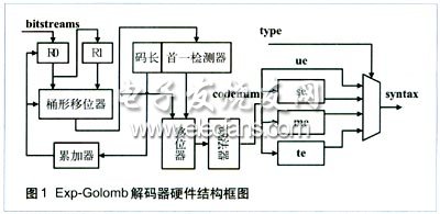
The hardware structure of the Exp-Golomb decoder designed based on the above decoding algorithm is shown in Figure 1. The entire system is mainly composed of the following modules: input code stream buffer shift module, code length detection module, codenum generation module, and syntax element mapping module. After the system is powered on and reset, the code stream buffer shift module first provides the word to be decoded, and then the first detector in the code length detection module detects the number of consecutive 0s, and the current code length is calculated immediately and sent to the accumulator . At the same time, the result of the first detection is sent to the codenum calculation module together with the word to be decoded, and the codenum value is obtained by shifting and subtraction. Finally, the codenum is sent to the four mapping units for processing, and the final decoding syntax element is output to the register by the selector. The entire decoding process is completed in one clock cycle. The hardware structure of each functional sub-module will be described in detail below.
Input code stream buffer shift module
The input code stream buffer shift module is to realize H. The key module of 264 real-time decoding. Since the code length cannot be determined in advance in each variable-length decoding process, the next code word must be located while solving the code value. This requires that the module has the characteristics of fast response and parallel output. Because H. The maximum code length of the Exp-Golomb code defined in 264 does not exceed 32. The design uses two 32-bit registers, a 32-bit barrel shifter and an accumulator to achieve this function, as shown in the left end of Figure 1. Among them, the register Rn is responsible for reading data from an external module, and used as the input of the barrel shifter together with the register R1; in each decoding cycle, the barrel shifter moves out of the decoded stream while loading a new to be decoded Stream; while the accumulator counts the processed code length, transmits the shift length of the barrel shifter, and determines and controls the reading of R0 and the update of R1. This provides a continuous and uninterrupted code stream for subsequent processing units.
Dongguan Deli Plastic Co.,Ltd is a manufacturer specialized in the research, development ,plastic injection mould and making mass production with well-equipped facilities and strong technical force.
Our products are extensively used in household industry/electronic industry/automobile industry/building industry and other industries.
We have rich experience on one-stop solution, provide various services from new product design,prototype,mold making,mass production,assembly and logistics. The most important advantage is we have our own R&D team to help clients to turn ideas into actual parts. All of these engineers and designers have over 15 years experience in these plastic products fields.
We have a strict quality control system, an excellent management team and also a dedicated sales force, enable us to fulfill our commitment in high quality products and outstanding services.
If you are looking for a trustworthy supplier of customized items, please do not hesitate to contact us. We are always striving to establish a win-win partnership with customers from all over the world and help our partners to stay one step in front of your competitors.
Lazy Fan,Lazy Hand-Free Mini Fan,Lazy Neck Fan,Lazy Wearable Neck Fan
Guangdong Aiyimi Electronic Technology Co., Ltd. , https://www.seventreasuresfan.com