Generally, the switching transistor of the switching buck converter is serially connected in the circuit, and the switching transistor of the switching boost converter is connected in parallel with the load, and the components connected in series with the load are an inductor coil and a diode. Therefore, if these two converters are used as backups, when the power supply is in the standby state, the buck converter cuts off the path of the input terminal due to the switching transistor, and the standby power consumption is small, and the current consumption is below 1 uA. But the boost converter is not. Although the switch tube is cut off but does not cut off the DC path between the input terminals of the input, the battery still forms a DC loop through the inductor and the diode and the capacitor and voltage detecting resistor at the output end, and the current flowing is about several tens of microamperes. In addition, a current flows through the load, and the magnitude of the current varies depending on the circuit.
In order to reduce this current loss, the following two methods can be employed.
1. Set the switch between the input and output
A switch is placed on the line between the input and output terminals, and Vin and Vout are separated in standby. The switch can be a mechanical switch such as a relay, or an electronic switch composed of a MOSFET.
Recently, the manufacturer has produced a boost converter IC with a load cut-off function, and the circuit shown in Fig. 1 is used. By the turn-off of the P-channel MOSFET Tr2 during standby, the DC path of the input terminal and the output terminal is cut off.

Figure 1 Setting the switch between the input and output
2. Using a transformer for isolation
As shown in Figure 2, the inductor is no longer used between the input and output, but instead the transformer is used. When the switch Tr1 is turned off during standby, the circuit is cut off, and the standby current of the switching power supply can be controlled to be less than 1 uA.

Figure 2 is isolated with a transformer
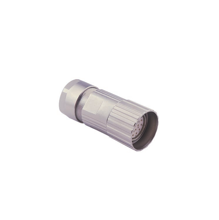
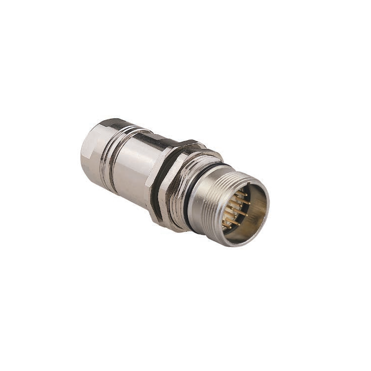
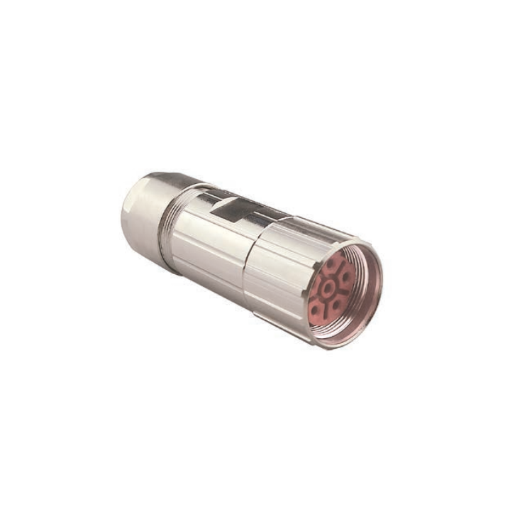
M23 series connectors provides a wide range of metric for small Sensors and actuators.The ingress protection is available and rated to IP 67, these connectors are ideally suited for industrial control networks where small sensors are required. Connectors are either factory TPU over-molded or panel receptacles supplied with sold-cup for wire connecting or with PCB panel solder contacts. Field attachable / mountable Connector is also available for your choice.


M23 Connector,Custom M23 Servo Connector,Mid Fixed Connector,M23 Panel Connector
Kunshan SVL Electric Co.,Ltd , https://www.svlelectric.com