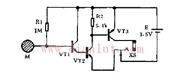
The detector circuit is shown in the figure. VT1~VT2 form a three-pole direct-coupled small-signal amplifier. M is the induction head, which picks up the 50Hz AC signal and sends it to the VT1 base for amplification. After the signal is amplified by three poles, it is output by the VT3 collector, and is added to the 8Ω low-resistance earplug via the jack XS to make it play. R1 is the base bias resistor of VT1. Its resistance value determines the two-stage static working power supply of VT1 and VT2. Under normal circumstances, it cannot be debugged. R2 is the VT2 collector load resistor, canceling R2, although the detector can work, but the static power consumption is too large. After accessing R2, it can effectively reduce the quiescent current of VT3 and save power consumption.
Smd Speaker,Smd Subwoofer,Mini Smd Speaker,Smd Piezo Speaker
NINGBO SANCO ELECTRONICS CO., LTD. , https://www.sancobuzzer.com