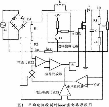
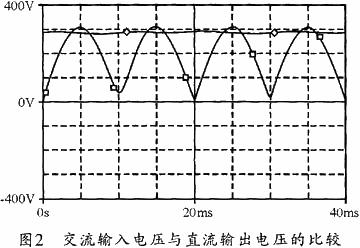
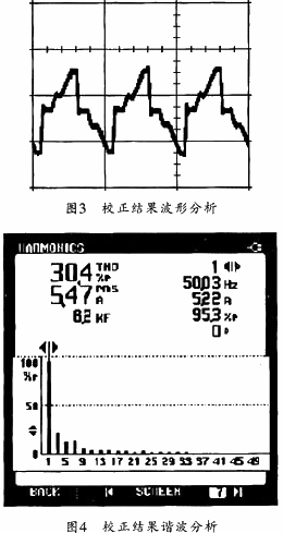
| 0 Introduction In recent years, with the development of electronic technology, the current harmonics and reactive power generated by various electronic devices and household appliances have attracted more and more attention to the pollution of the power grid. The existence of harmonics not only greatly reduces the power factor of the input circuit, but also can cause pollution to the public power system and cause circuit failure. In order to suppress the harmonics of the power grid and reduce the current pollution, the international standard has begun to restrict the higher harmonics in the form of legislation. China has also promulgated relevant national standards, and electrical products can only enter the market if they meet the corresponding harmonic standards. Current rectifiers using active power factor correction (APFC) circuits have become the mainstream method for suppressing harmonics. To this end, this paper presents a new PFC design scheme for air conditioning designed by Boost-type power factor correction under the control of average current technology. 1 Basic method of power factor correction The power factor correction method can be divided into passive power factor correction and active power factor correction. The passive power factor correction structure is simple and easy to implement, but the corrected power factor is not high. Active power factor correction involves adding a power converter between the bridge rectifier and the output capacitor filter to correct the input current to a sine wave that is in phase with the input voltage and is not distorted, resulting in a power factor close to one. The active power factor correction structure is complicated, but the correction effect is better. It is currently a widely used power factor correction method. According to the circuit structure, active power factor correction can be divided into buck, boost/buck, flyback, and boost. The boost topology uses a simple current-mode control method with high PF value and small total harmonic distortion (THD), which is the most widely used. The output voltage of this method is higher than the input voltage, which is more suitable for 75~2 000 W. According to the input current control principle, active power factor correction can be divided into average current type, hysteresis current type, peak current type, and voltage control type. Among them, the average current mode control operating frequency is fixed, the input current is continuous, and the effective value of the switch tube current is relatively small, so it is more suitable for medium power and higher power. Although its control circuit is more complicated, it is still widely used. This article uses the PFC circuit of the average current control type boost architecture. 2 circuit design At present, frequency conversion technology is increasingly used to control the operation of air conditioners, which makes the requirements of power factor correction more practical. The widely used frequency conversion technology is to obtain a relatively stable DC power supply after the power supply provided by the power grid is rectified and filtered, and then use the PWM technology to chop the sine wave with adjustable frequency and amplitude to achieve convenient frequency conversion speed control and energy saving. The purpose of control. Figure 1 shows a schematic diagram of a boost-type circuit using average current control. The circuit generates a reference current signal by comparing the output of the rectifier bridge output voltage detection signal with the voltage error amplifier output signal to provide a PWM signal to the switching transistor. The PFC circuit is essentially a non-linear, periodic time-varying switching system. First, its input is a full-wave rectified waveform; second, the circuit contains two modulations: one is sinusoidal pulse width modulation and the other is amplitude modulation. These two modulations interact with each other under negative feedback, thereby controlling the current waveform to track changes in the voltage waveform.  The circuit uses a dual closed-loop feedback design of voltage and current. The voltage loop (outer loop) stabilizes the output voltage signal, and the current loop (inner loop) allows the input current to track the input voltage waveform well for better power factor correction. . The voltage loop does not compare the output DC voltage Uo with the reference voltage Vref and inputs the generated voltage feedback signal to the multiplier. The current loop design uses a voltage error amplifier and a rectified DC voltage Ud to generate a current reference signal through a multiplier, and then compares the sampled inductor current Iac with the reference current, and processes it through a current error amplifier, and then generates The signal voltage is compared with the sawtooth wave to determine the on and off of the power switch and the duty cycle, which ultimately enables the inductor current to follow the reference current, thereby effectively increasing the power factor. The control circuit structure of the system can be roughly divided into an IGBT chopper control circuit, a voltage zero-crossing detection circuit, a voltage amplitude sampling circuit, a current sampling circuit and the like. 2.1 IGBT chopper control Because the power factor correction controller used in inverter air conditioners needs to work for a long time under high power conditions. Moreover, when the power is large, the conventional APFC power device is subjected to a large current stress, which makes the device selection difficult, increases the product cost, and affects the stability of the system. Therefore, in order to effectively improve the power factor, reduce the requirements on components and reduce component losses, the design has been improved on the basis of the traditional APFC, thereby avoiding the current peak, that is, using partial chopping in each voltage cycle. The chopping control method. Compared with the APC control method of all chopping in the whole cycle, adopting this new chopping method will reduce the power factor correction effect to a certain extent, which is not conducive to the suppression of higher harmonics, but it is needed in the process of electrical productization. Considering efficiency and cost, the control effect and system cost can be optimally combined by controlling with appropriate chopping timing. In this design, the switching frequency of the IGBT is selected to be around 16 to 20 kHz. In the IGBT chopper control, in order to effectively reduce the switching loss of the device, both power factor correction and harmonic suppression are achieved, and the appropriate switching timing is selected according to the AC input voltage and the output voltage and load variation. It has become the key to a system circuit design. Through multiple simulations and experimental studies, the system uses a design method that compares the input AC voltage and the output DC voltage amplitude to control the chopping timing. Figure 2 shows the simulated waveforms with PSPICE 9.1. As can be seen from the figure, as long as the appropriate circuit parameters are set, when the AC input voltage Ui of the power supply is 220 V, the DC output voltage Uo fluctuates slightly around 290 V. Therefore, the voltage amplitude sampling circuit can be used to obtain the AC input voltage and the DC output voltage amplitude, and then compared by a comparator. When the amplitude of the input AC voltage Ui is greater than the output DC voltage Uo, the IGBT can be controlled to stop chopping by the chopper control signal comparator, and the chopping starts when the input AC voltage amplitude Ui is smaller than the output DC voltage Uo. In fact, the input voltage is greater than the DC output voltage at the peak, so the switching device can be controlled to stop chopping.  2.2 Voltage Zero-crossing Detection Circuit In order to keep the input current and the input voltage in phase, the input voltage zero-crossing detection must be performed during design. In Figure 1, the voltage is detected by Rl, R2 and the signal is input to the transistor T1. When the input voltage passes the zero-crossing point, the transistor is turned on, and the corresponding output port level of the link will be clamped to zero for the signal. Can be completely input to the interrupt port of the CPU; when the instantaneous value of the input AC voltage is close to zero, the triode is turned off, the circuit sends a high level signal to the CPU interrupt port, and the CPU controls the current through the level shift signal to make the input current Ability to track changes in input voltage. 2.3 Voltage amplitude sampling circuit Since the IGBT chopping timing in this system is controlled by comparing the AC input voltage and the DC output voltage amplitude, the voltage amplitude sampling circuit is particularly important in this circuit, it will directly Affects power factor correction and harmonic suppression. Voltage amplitude detection includes input AC voltage amplitude detection and output DC voltage amplitude detection. This design divides the instantaneous value of the input AC voltage by voltage divider R1 and R2, and inputs it into the CPU for A/D conversion. The DC input voltage amplitude is divided by the resistors R3 and R4 and then input into the CPU for A. /D conversion. 2.4 Current Sampling Circuit A simpler current sampling circuit is used in this design, and the current is detected by the resistor Rac. When current sampling is required, the current to be sampled is converted to the voltage across the small resistor Rac in the external circuit and input to the A/D converter port of the CPU for current sampling. 3 Test results After the PWM chopping control of the power factor correction circuit, the input current in the circuit can basically follow the change of the AC input voltage, and the higher harmonics are effectively suppressed. Figure 3 shows the waveform of the power factor correction test using the boost-type circuit of the new average current control described in this paper. It can be seen from the figure that the corrected waveform is closer to the sine wave than before the correction. Figure 4 shows the harmonic analysis of the calibration results. It can be seen from Figure 4 that after using the design method of this paper, the PF value can reach above 0.95, and the higher harmonics do not exceed the national harmonic standard. The control results are in full compliance. The use requirements of household appliances such as inverter air conditioners effectively reduce component requirements and improve system stability.  4 Conclusion Based on the analysis of traditional PFC, this paper proposes a new PFC control scheme applied in inverter air conditioner products, and further simulates and tests the scheme. The result proves that it is turned off at the peak of current. The new power factor correction method of the switching device can effectively reduce the requirements on the switching device and reduce the system loss, and the corrected PF value reaches 0.95 or more. |
:
0 times
Window._bd_share_config = { "common": { "bdSnsKey": {}, "bdText": "", "bdMini": "2", "bdMiniList": false, "bdPic": "", "bdStyle": " 0", "bdSize": "24" }, "share": {}, "image": { "viewList": ["qzone", "tsina", "tqq", "renren", "weixin"], "viewText": "Share to:", "viewSize": "16" }, "selectShare": { "bdContainerClass": null, "bdSelectMiniList": ["qzone", "tsina", "tqq", "renren" , "weixin"] } }; with (document) 0[(getElementsByTagName('head')[0] || body).appendChild(createElement('script')).src = 'http://bdimg.share. Baidu.com/static/api/js/share.js?v=89860593.js?cdnversion=' + ~(-new Date() / 36e5)];

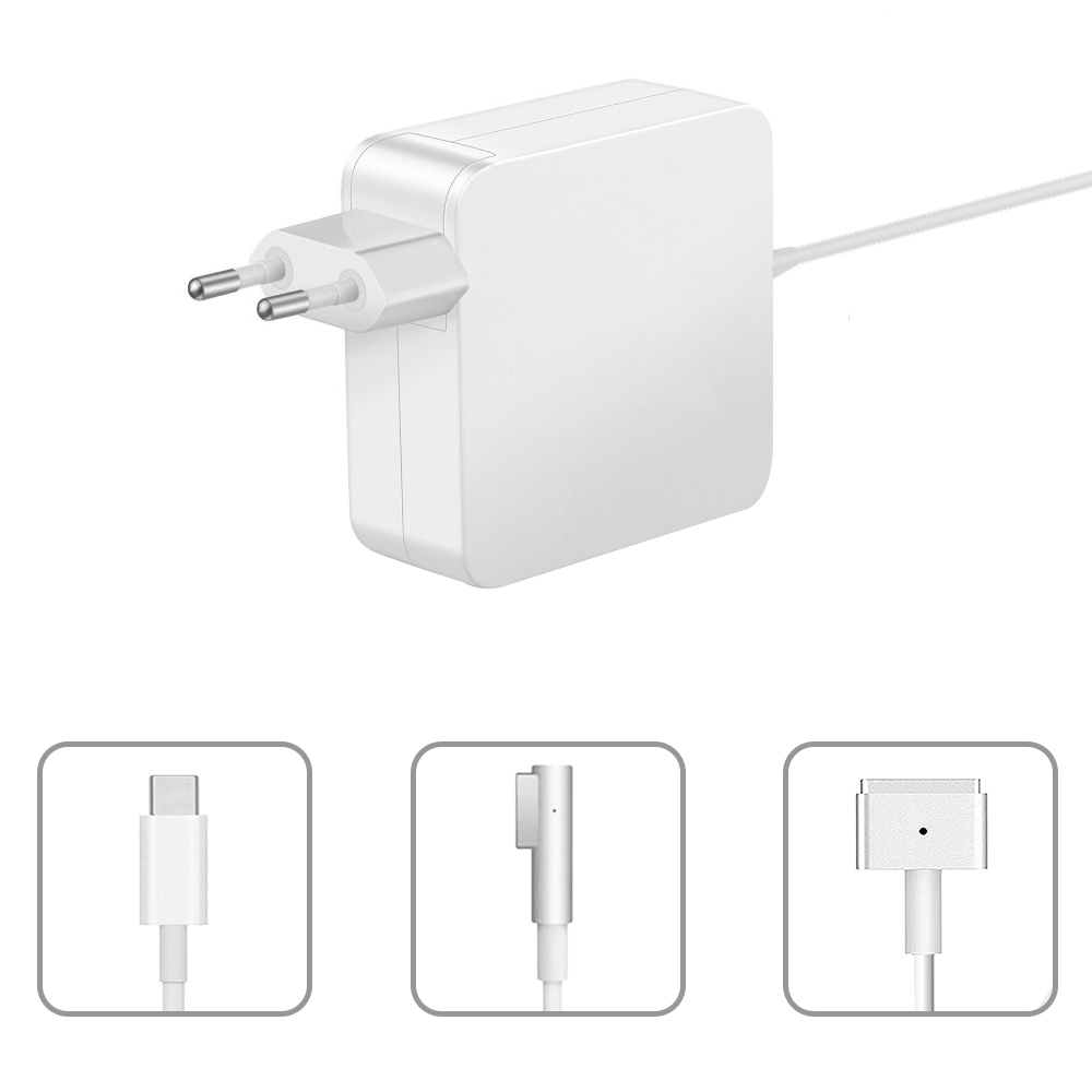
The 45W MagSafe Power Adapter has a magnetic DC connector, so if someone trips on it, the power cord disconnects harmlessly, keeping your MacBook Air safe. It also helps prevent the cable from fraying or weakening over time. Additionally, the magnetic DC helps guide the plug into the system for a quick and safe connection.
45W Macbook charger air,macbook 45watt charger,45W Macbook pro charger
Shenzhen Waweis Technology Co., Ltd. , https://www.laptopsasdapter.com