Fanuc 3D Vision Application
1
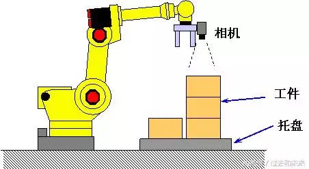
iRVision 2.5D Visual Stacking
The visual stacking program estimates the height of the target by the change of the target scale in the camera field of view and guides the offset of the motion compensation target of the robot, including not only the X-axis, the Y-axis and the XY plane rotation R, but also the Z-axis.
Using iRVision 2.5D allows the robot to pick up the target of stacking and stacking with just one ordinary 2D camera.
2
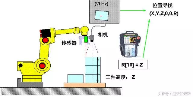
iRVision Vision Stacker_1 (Z-axis offset from register R)
This function visually calculates the 2D position of the target and the specified register value, and guides the robot's motion compensation target offset, including not only the X-axis, the Y-axis and the XY plane rotation R, but also the Z-axis.
The register R is used to store the known target Z-axis height or the Z-axis height information detected by the distance sensor.
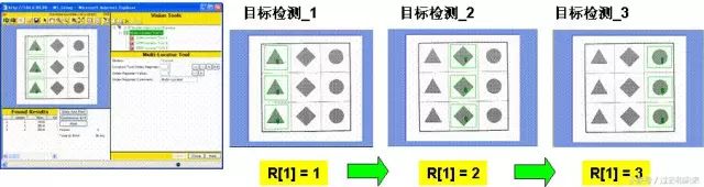
3
RVision Vision Stacker_2 (Extract Z-axis offset from stacking layer)
This function calculates the position of the target by visually combining the visual inspection result with the target number of layers (target height) determined according to the target ratio. The number of target layers is automatically determined according to the reference scale and height data, so that even if there is a slight proportional error in the visual inspection, the specific position of the target can be calculated by a discrete number of layers (target height).

4
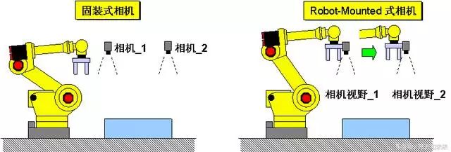
iRVision 2DV complex view function
The 2D Complex Field of View program provides the ability to locate large targets with a number of fixed cameras for use with Robot-Mounted cameras
It is also effective to perform the test.
5
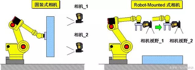
iRVision 3DL complex view function
The 3D complex field of view program provides the ability to locate large targets with a number of fixed 3D cameras, as well as for detection by Robot-Mounted cameras.
6
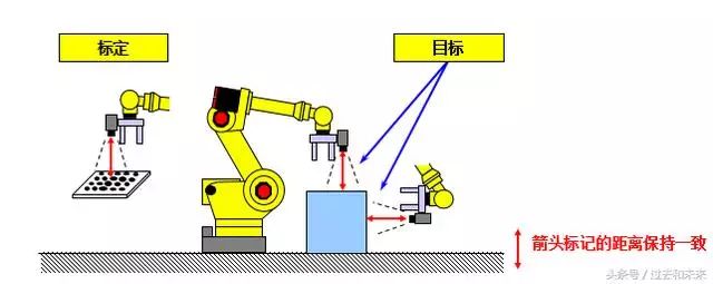
iRVision Floating Coordinate System Function (Floating Frame)
The calibration of the Robot-mounted camera can be used for the iRVision program in any position and orientation as shown below. The motion compensation in the 2D state is associated with the actual camera position. The calibration of the camera can be performed at any position. Reduce the amount of teaching work.
7
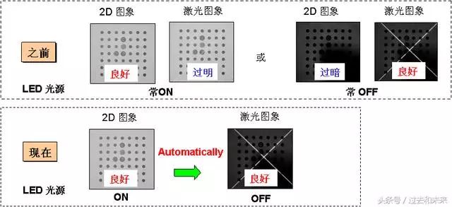
iRVision 3DL LED Light Source Control
This feature supports simultaneous control of the ON/OFF of the LED source during capture of 2D images and laser illumination in the 3DL vision program. With this feature, you can get the right external lighting environment and enhance the capabilities of the entire vision system.
8
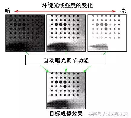
iRVision auto exposure
Depending on the intensity of the surrounding ambient light, iRVision will automatically adjust the exposure time to achieve similar imaging results as teaching a good image, running around the clock.
9
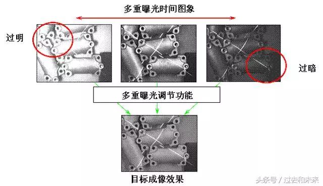
iRVision multiple exposure
By imaging multiple different exposure times, an image close to the teaching effect is selected to achieve a broad, dynamic exposure range and imaging effect. This function will have a good effect when the ambient light changes strongly.
10
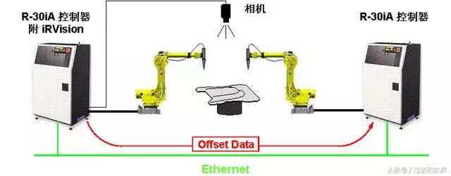
iRVision ring network function (Robot Ring)
With this function, robots without the iRVision vision system can call the offset detection data of the robot with the iRVision vision system via the network.
11
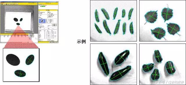
iRVision Blob Locator Tool
A binary (black and white) target position having similar characteristics (such as circumference, curvature, etc.) to the teaching model is detected within the imaging range. Used in conjunction with the Conditional execution tool, it can be applied to a variety of occasions such as target alignment and quality inspection.
12
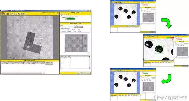
iRVision grayscale detection function (Histogram Tool)
The light intensity (imaging gradation) is detected in a specified area, and various characteristics such as an average value, a maximum value, a minimum value, and the like are calculated. Used in conjunction with the Conditional execution tool, it can be used in a variety of situations, such as target alignment and target in-position detection.
This function is equivalent to the Associate tool in the V-500iA/2DV.
13
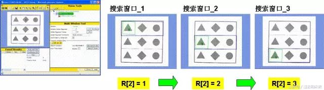
iRVision Multi-Window Detection (Multi-Window Tool)
The corresponding preset search window is switched by the value change of the register R in the robot controller.
14
iRVision Multi-Locator Tool (Multi-Locator Tool)
The corresponding preset target visual program is switched by the value change of the register R in the robot controller.
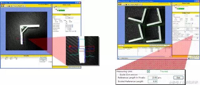
15
iRVision Length Measurement (Caliper Tool)
Corresponding to the specified area, detecting the target edge and measuring the length between the two edges (unit: pixel pixel), multiplied by the conversion factor can be converted to mm. It can be used for applications such as target alignment and quality inspection.
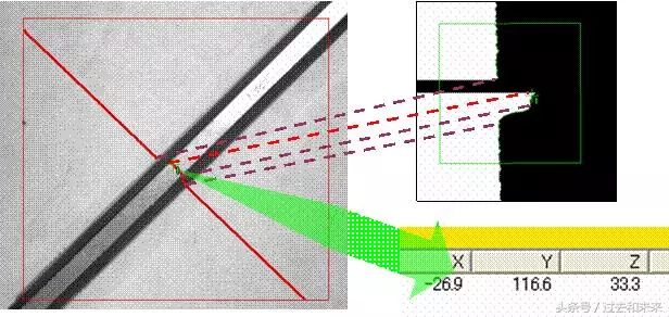
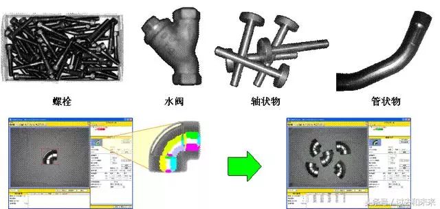
16
iRVision section detection function (Cross Section)
The local 3D characteristic of the target is detected, showing the shape of the target section along the path of the laser ray. It is more effective in the 3D visual program because 2D imaging lacks an effective feature quantity and cannot be accurately positioned.
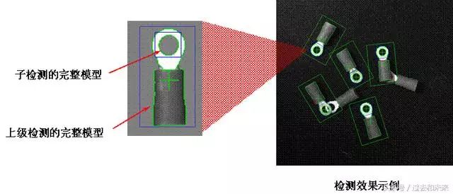
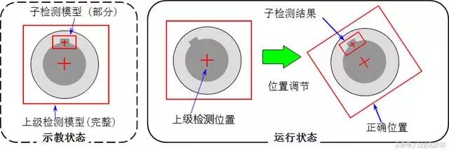
17
iRVision sub-detection function (Child Tool)
A sub-target detection (GPM locator tool) is allowed to form a secondary detection directory under a parent target detection (GPM locator tool). The subtest will make a dynamic decision based on the result of the parental test. Used in conjunction with the Conditional execution tool, it can be used in a variety of situations, such as target alignment and target in-position detection.
18
iRVision Positioning Adjustment (Position Adjust Tool)
According to the result of the sub-detection, the obvious features (such as holes and keyways) of the target surface are adjusted to adjust the position of the parent detection to obtain more accurate offset and rotation data. It is more effective for applications that cannot be directionally positioned with the entire teaching model. For a superior detection, multiple sub-detections can be used to analyze multiple local characteristics of the target.
19
iRVision Surface Matching Tool (Curved Surface Matching Tool)
The offset and rotation of the surface target are detected by a stepwise light intensity distribution of the target surface (light or dark, displayed in the model as a different color). Identify full circular objects possible.
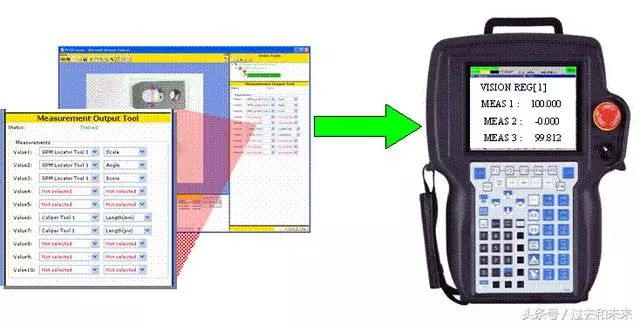
20
iRVision Measurement Output Tool
The measurement value ("Score/point value", "Size/scale" in the Locator tool, "Length/length" in the Caliper tool, etc.) is output to the visual register VR. These data can be copied to the robot data register R and freely called in the TP program.
twenty one
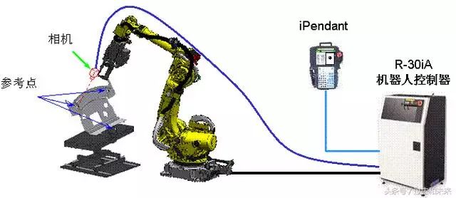
iRVision Vision Shift (Vision Shift)
By adjusting the robot TP program through the visual program to correspond to the actual workpiece position, you can perform this function by simply adding a camera to the robot's grip. The position data of any three reference points on the fixed workpiece will be automatically detected and the compensation data will be calculated.
After offline programming or robot system relocation, using this feature can greatly reduce the time for the robot to re-teach.
twenty two
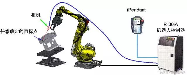
iRVision Vision Mastering
To compensate the zero data of the robot J2~J5 axis through the visual program, you only need to add a camera to the end of the robot to perform this function. The robot changes the different poses, and the relative position data between the camera and the determined target point is automatically detected and the compensation data is calculated.
This feature can be used to improve robot TCP teach accuracy, Vision shift offline programming and other visual applications.
twenty three
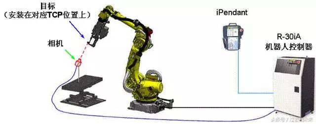
iRVision Vision Coordinate System Setting Function_1 ( Vision Frame Set)
To set up the robot TCP through the visual program, you can perform this function by simply adding a camera to the corresponding position of the TCP end of the robot. The robot transforms different poses, and based on the relative position data between the camera and the target point in the corresponding user coordinate system, the robot corresponding TCP is automatically detected and calculated. This feature improves the speed and accuracy of TCP teach.
twenty four
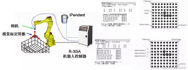
iRVision Vision Coordinate System Setting Function_2 ( Vision Frame Set)
Another function of the coordinate system setting: visually set a user coordinate system that is equivalent to the visual calibration board. The user coordinate system UF is set at the origin position of the visual calibration plate (four-point method) by the camera at the end of the robotic gripper, or when the visual calibration plate device is at the end of the robotic gripper, the tool coordinate system UT is set on the visual calibration plate. The origin position (six-point method).
Our factory can produce the substation structures, 35KV, 110KV, 220KV, 500KV various steel components, A shape structures.
Substation Structures,Substation Steel Structures,Structure Of Substation,Substation Steel
Jiangsu Baojuhe Science and Technology Co.,Ltd. , https://www.galvanizedsteelpole.com