Adjustable capacitor Murata genuine original
TZC3Z060A110R00 MURATA Murata adjustable capacitor original spot
Circuit Operation Principle The multi-function fading and governor circuit consists of a power supply circuit, a timing control/trigger pulse generator circuit, and a control execution circuit, as shown in Figure 3-163.
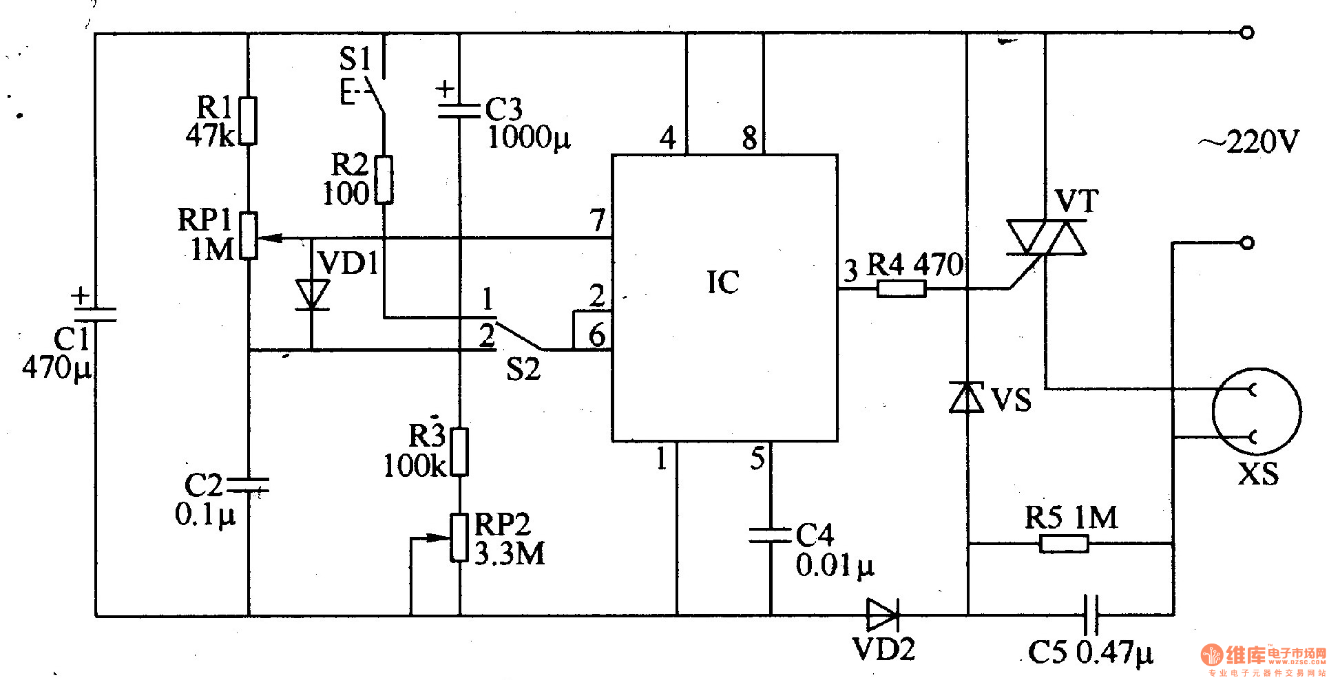
The power circuit is composed of a step-down capacitor C5, a Zener diode VS, a rectifier diode VD2, and a filter capacitor Cl.
The timing control/trigger pulse generator circuit is composed of a time base integrated circuit IC, a control switch S1, a timing/voltage regulating selection switch S2, a resistor Rl-R3, a potentiometer RP1, a R-tooth, and a capacitor C2-C4.
The control execution circuit consists of a resistor R4 and a thyristor VT.
AC 220V voltage is reduced by C5, resistor R5, VS voltage regulator, VD2 rectifier and Cl filter, providing +I2V (Vcc) working voltage for IC.
When S2 is placed in the "1" position, the IC and peripheral components form a timing control circuit. When using, press S1, C3 will quickly discharge through R2 and S1, so that the 2 pin and 6 pin of the IC are high, the 3 pin outputs low level, the VT is triggered and turned on, and the power socket XS has voltage output. At the same time, the +l2V voltage is charged to C3 via RP2 and R3, so that the voltage of the 2 pin and 6 pin of the IC is gradually decreased. When the voltage of the two pins is reduced to the memory of 73, the 3 pin of the IC outputs a high level, so that the VT is cut off. The timing time is over. The AC voltage on the XS disappears. Adjusting the resistance of RP2 can change the charging time of C3, thus changing the time to turn off the power at regular intervals.
When S2 is placed in the "2" position, the IC and peripheral components form the trigger pulse generator circuit. The IC's 3-pin output frequency is about I3Hz, and the duty cycle is adjustable. It is used to control the conduction angle of VT. Adjusting the resistance of RPl, you can change the width of the trigger pulse, control the size of the VT conduction angle, and make the AC output voltage (power) on the XS change with the change of the VT conduction angle, thus achieving the purpose of voltage regulation.
Component selection
Rl-R5 uses 1/4W carbon film resistor or metal film resistor.
Both RPl and RP2 use organic solid potentiometers.
Both Cl and C3 use aluminum electrolytic capacitors with a withstand voltage of 16V; C2 and C4 use monolithic capacitors or polyester capacitors; C5 uses CBB capacitors with a withstand voltage of 400V or higher.
VDl selects 1N4148 or 2CKg type silicon switch diode; VD2 selects 1N4007 type silicon rectifier diode or 2CP21
VS selects 1N4742 type (lW, l2V) silicon steady voltage diode.
VT uses 6A, 600V two-way crystal tube. To control high power loads (electrical appliances), increase its current capacity.
IC selects NE555 or SC1555, SU55, μA555 type time base integrated circuit.
S1 selects the dynamic (normally open) button; S2 selects the single-pole double-position toggle switch.
Cell Phone Case, Mobile Phone Covers, Clear Phone Case, Mobile Phone Case, TPU Phone Case, Silicone Phone Case
Shenzhen Jianjiantong Technology Co., Ltd. , https://www.jonsun-sz.com