I. Introduction
With the release of the AMD Ruilong processor, the DIY market, which has been filled with raw water, has suddenly ushered in a small surge of installed capacity. Even if memory, SSD, and a series of accessories brought by the tidal wave have skyrocketed, it still can't stop everyone from installing. enthusiasm. I also started a set of RYZEN 7 1700 sets in this small trend. It was originally installed in the old chassis. Recently it was fortunate to have a cool mother's latest release of the chassis - Rui, the "old platform" into the new chassis, and conduct a simple little evaluation.
Second, the product description
Before installing the machine, we first come to understand the parameters of the next Rui. The box size is: 468.8X200X454.5mm, the weight of the box is 5.04KG, and the size is appropriate. It does not appear to occupy the position on the desktop. Because the side and front panels are made of acrylic material, the weight of the empty machine is about 5KG, and the thickness of the sheet is 6mm (some 5mm), also considered quite satisfactory. Chassis has no optical drive, video card support is 40mm, radiator support is 160mm support, and a 12mm fan is standard.
Wikipedia CoolMaster MasterBox Lite 5 (Rui) mid tower chassis (ATX motherboard / front mirror panel / large side through / long graphics / independent power supply compartment) MasterBox Lite 5 retains the Department of the tough simple lines, internal expansion is not Vulgar, also has a good water-cooled and air-cooled expansion, to meet the needs of the mainstream high-end gaming platform. The design continues the Master's minimalist and calm design concept. The Box Lite 5 is separated from the traditional chassis fixed mode, using a plastic side panel, the front panel also uses a polyhedral mirror design, the internal fan is lit, the fan light value 18 comments 0 Original 0 Good 5 to buy View Details
 Third, evaluation configuration
CPU: RYZEN 1700
Radiator: Original Belief RGB Radiator
Motherboard: ROG B350-F
Memory: Mirage 3000X2
Graphics: Sapphire RX460 (I hate miners  )
)
Hard Disk: Samsung 850EVO 240G
Power Supply: EVGA 650W Full Module
Chassis: Cooler Master - Rui
 888
888
Fourth, the chassis analysis
First of all, we first come to the front of the chassis (Please ignore the mirror in the body..) 
 1
1
We can see that the front of the chassis is a full-covered high-transmitting, high-reflective acrylic. After we open the panel, we can see that the chassis can have a maximum of three front-mounted 12mm fans or two 14mm fans. Here I first load two. 12mm fan to see the effect.
 9
9
The left side plate is also an acrylic high-penetration baffle with four hand-screws on the four corners for easy removal. There are also four rubber mats around the perimeter, and the rims have been treated with sand.
 2
2
Let's look at the back of the chassis. On the back of the chassis, we can see a 12mm rear fan. The PCI bit of the graphics card is recessed inwards. Here you need to mention that if you install an additional wireless network card on the motherboard, you can be pleasantly surprised to find that it may be recessed. The PCI card oh.... 
 3
3
 3-1
3-1
 3-2
3-2
Looking at the power supply again, here is one of my favorite designs, a removable drawer-type power supply. You can fix the power supply on the bezel beforehand, and then fix the power supply with the left and right movable screws and push the power supply into the power supply slot.
 3-3
3-3
The top of the chassis is a complete galvanized top plate, why can't it open the hole to support the upper heat dissipation? This way, the heat dissipation of this chassis can definitely be on a grade, and the reasons will be explained later.
 4
4
I also liked the design of the IO panel. It was designed to be tilted so that if your computer desk is closed, you don't have to worry about plugging the U disk against the computer desk. From left to right, the IO panel is a reset button, an audio interface, a button BOOM (power switch), two USB 3.0, and finally a hard disk indicator. After the power button is turned on, there is a white LED aperture.
 4-1
4-1
There is a row of small thermal holes underneath the IO panel.....there is also a row of cooling holes and a dust-proof net at the front, slightly larger. Looking at this area, I can't help but worry about the air duct of the chassis. After all, there is no top Heat vents.
 4-2
4-2
 4-3
4-3
The right side is nothing better than a complete backplane. 
 5
5
Now we look at the bottom if there is a surprise. There are four trapezoidal rubber corner pads on the bottom for non-slip shock absorption and increased bottom air flow. Power outlets also have removable dust nets. 
 6
6
 6-1
6-1
With the side panel removed, you can see the spacious motherboard mounting space inside, supporting ATX MATX MITX motherboards. The following is the power isolation compartment, where you can also install two 2.5-inch hard disk vents, and there are two large routing holes on the top to facilitate your line.
 7
7
 7-1
7-1
There are two SSD hard disk installation positions on the right side of the motherboard, but only one hard disk tray (EXCUSE ME?) is installed. After installing the SSD here, you can display your SSD through the side panel....
 7-2
7-2
 7-3
7-3
Finally we removed the backplane. There are multiple tie lines on the back cabling area to facilitate various cabling. The power supply compartment supports a maximum of 17 CM long power supply. Next to the two 3.5-inch hard disk tool-free mounting brackets, the area next to the blank can hide your hands and walk away. line....  There is also a surprise place in the power supply compartment, there are four damping nails, more surprising is that these four nails are very easy to fall ...
  This point needs to be modified. It may be better to change it into a fixed damping nail.
 8
8
 8-1
8-1
 8-2
8-2
Fifth, installed appreciation
Well, after reading the chassis, we will put the platform into it. . Let's take a look at my lazy line... 
 10
10
Look at the front again.
 11
11
 12-1
12-1
 12-2
12-2
 12-3
12-3
 12-4
12-4
to sum up

advantage:
1. The overall space is adequate, and there is no pressure to place personal hands.
2. The inclined IO panel is easy to use.
3. The design of the power supply compartment is very user-friendly.
4. Dust prevention and shock absorption measures are in place.
Disadvantages:
1. The high lens surface is easy to scratch, and the side panels are vulnerable to perspiration and stains.
2. Insufficient heat dissipation, it is recommended that the top opening increase the heat sink.
3. The power damping nails are easy to fall off and affect their use.
4. The PCI bit design does not take into account the needs of the wireless extension card, and it is recommended to modify it.
In short, in the 299 yuan chassis price, Rui this product is worth recommending, but in terms of heat dissipation is not satisfactory, if you can increase the top heat, optimize the front vent hole, then this chassis can attract more people to buy .
Thank you again for your appreciation, thanks 
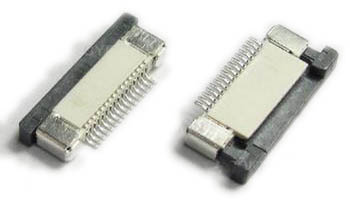
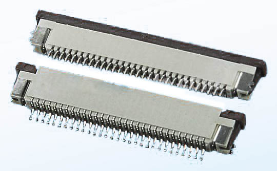
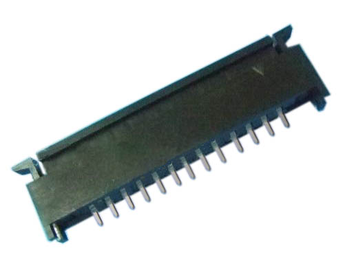
1.ANTENK Flexible Printed Circuit (FPC) and Flexible Flat Cable (FFC) connectors are ZIF (zero insertion force) and LIF (low insertion force) connectors designed to provide a fast, easy, reliable method to make a connection of flexible printed circuits to a PCB. Adam Tech`s special contact design completely preserves conductor integrity by eliminating all wiping action while making connection. Flex circuitry enters the connector and the connector cap is pressed down to capture the flex circuit producing a stable, high pressure connection. Raising the cap releases the pressure for exchange or replacement of circuitry. This series includes single and dual row versions in thru-hole or SMT mounting in vertical or horizontal orientations.
2.Our products are widely used in electronic equipments,such as monitors ,electronic instruments,computer motherboards,program-controlled switchboards,LED,digital cameras,MP4 players,a variety of removable storage disks,cordless telephones,walkie-talkies,mobile phones,digital home appliances and electronic toys,high-speed train,aviation,communication station,Military and so on


FFC Connector Range Available as:
0.3,0.5, 0.8, 1.0,1.25, 2.54mm connector pitch
Surface mount
Side and Top entry
Side entry parts - Top and bottom contact options
ZIF (Zero Insertion Force)
Slide and flip lock actuator styles
Specifications:
Material And Finish:
Insulator: LCP
Lock: PPS
Insert Spring:Phosphor Bronze,
Matte Tin Plated
Solder Platten Area:Phosphor
Bronze,Matte Tin Plated
Voltage:500 V AC(rms)/DC
Current:0.5 A AC(rms)/DC
Contact Resistance:20 mΩ max(initial)
Insulation Resistance:800 MΩ min
Operating Temp:-20°-85°
Fpc Connector,Fpc Cable Connectors,Ffc Cable Connectors,Pitch Fpc Connector,Surface mount FPC/FFC Connectors,Top entry FFC Connectors, Side entry FFC Connectors
ShenZhen Antenk Electronics Co,Ltd , https://www.pcbsocket.com