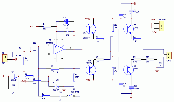
IC + emitter cross output pre-stage
Since this PCB board will be used in the headphone amplifier circuit in the future, it should first be stated that the requirements of the headphone amplifier and the previous stage are different. According to my understanding: to ensure that various distortions are small and the signal-to-noise ratio is high In the case of, the frequency response required by the front stage is straight, and the phase shift should be as small as possible. As for the headphone amplifier, since the headphone is an inductive load, it is necessary to match the frequency response and the phase shift.
See the circuit diagram for component specifications (if the schematic diagram and the value on the PCB board are different, please refer to the schematic diagram).
First of all, ensure that the power supply voltage is between + -15V and + -22V. In order to meet the requirements of most op amps, the power supply voltage can be selected at + -18V. As long as the components are installed correctly and the power supply voltage is correct, there is generally no need to adjust. If you want to further modify the sound quality, you can consider starting from the following aspects. 
The circuit looks very simple, that is, a single op amp plus a "emitter cross output" to expand the current, the emitter cross output, I first saw it used in the video circuit for buffering, it can be seen that the working frequency of this circuit The scope is still very wide. Because the circuit uses cross-output and direct coupling, an important conclusion can be obtained by analyzing the circuit: the thermal stability of this circuit is very good.
However, this circuit has a fatal shortcoming that it can only work in pure Class A state, and the output voltage range is not very large. Fortunately, our use is for pre-amplification. These shortcomings are irrelevant to us.
The design of the circuit is specially prepared for audiophiles. In order to give the producers a larger space for motorcycles, and to give full play to each enthusiast's understanding of HI-FI, there is a lot of room for design on the PCB board. By adjusting the values ​​and connection methods of different components, it can be made into a pure DC amplifier circuit or an AC amplifier, and the sound quality can also be modified by adjusting the components of the negative feedback network to achieve the effect of meeting your own listening requirements. |


![[Photo] RIAA circuit of IC + discrete parts](http://i.bosscdn.com/blog/20/06/41/513816449.gif)


![[Photo] RIAA circuit of IC + discrete parts](http://i.bosscdn.com/blog/20/06/41/513816449.gif)