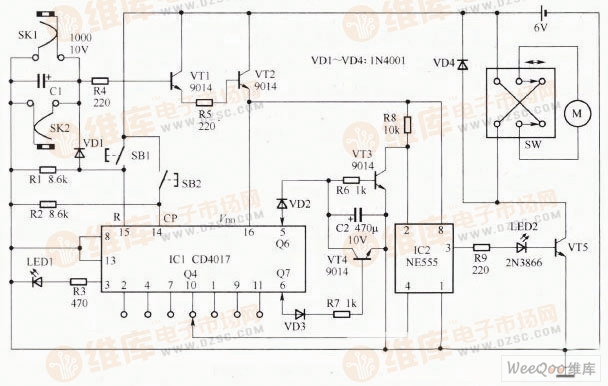
Precision electronic code lock circuit
The figure shows the circuit diagram of the precision electronic code lock. The circuit is composed of a jack switch, a password input switch, a bit error switch, an unlock program circuit and an unlock control circuit. SKI, SK2 form a jack switch, which is used to control the working power. SKI and SK2 are connected across the capacitor CI, and the CI can be short-circuited by the contact of the internal reed. At this time, the power supply cannot be added to TCI and TC2, and the circuit cannot work. When it is necessary to unlock, insert a special plug to separate the reed. At this time, press the switch SBI again, the circuit can obtain the working power and unlock the operation. SB1 is the power switch and error code switch, SB2 is the password input switch, press SB2 once, you can input a pulse to ICI. If the SB2 button is pressed 6 times and then pressed again during the unlocking process, the IQ Q7 output will be high. This high level will turn VT4 on, short-circuit C2 to end the charging delay process, and the second pin of IC2 returns to high level and cannot be unlocked.
Yoga Laptop,2-In-1 Yoga Laptop,Quad-Core Notebook,Notebook Computer Office,Folding Laptop
C&Q Technology (Guangzhou) Co.,Ltd. , https://www.gzcqteq.com