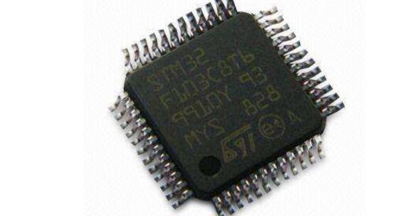
1. Speed, compared to 51 and AVR, is quite fast.
2. Capacity, currently available directly to 512K FLASH.
3. Pins, 64, 100, 144, etc. Unfortunately, small pins (less than 32 legs), no
4. RAM, 48K, too large compared to AVR's 4K.
5. Peripherals, 5 USARTs, 2 IICs, 2 SPIs, USB, etc., all commonly used.
6. Software, STM has its own firmware library that speeds development without having to look at registers.
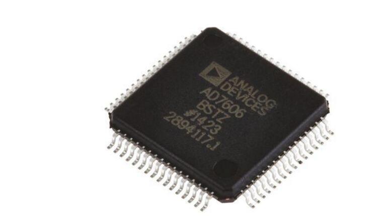
8/6/4 simultaneous sampling input
True bipolar analog input range: +10V, +5V
5V Single Analog Supply, VoRIVE: 2.3V to 5V
Fully integrated data acquisition solution
Analog input clamp protection
Input Buffer with 1 MQ Analog Input Impedance
Second-order anti-aliasing analog filter
On-chip precision reference voltage and buffer
16-bit, 200 kSPSADC (all channels)
Oversampling capability via digital filter
Flexible parallel/serial interface
SPI/QSPI "/MICROWIRE"/DSP Compatible Performance
Analog Input Channel Provides 7 kV ESD Rating
95.5dB SNR, -107dBTHD
0.5LSBINL, +0.5LSB DNL
Low power consumption: 100 mW
Standby mode: 25 mW
64-pin LQFP package
1, configure the STM32F103 SPI port
Void AD7606_Port_Init(void)
{
GPIO_InitTypeDef GPIO_InitStructure;
SPI_InitTypeDef SPI_InitStructure;
RCC_APB2PeriphClockCmd(AD_SPI_CS_GPIO_CLK | AD_SPI_MISO_GPIO_CLK | AD_SPI_SCK_GPIO_CLK, ENABLE);
RCC_APB1PeriphClockCmd(AD_SPI_CLK, ENABLE);
///////////////////////////SPI_CLK////////////////////////
GPIO_InitStructure.GPIO_Pin = AD_SPI_SCK_PIN;
GPIO_InitStructure.GPIO_Speed ​​= GPIO_Speed_50MHz;
GPIO_InitStructure.GPIO_Mode = GPIO_Mode_AF_PP;
GPIO_Init(AD_SPI_SCK_GPIO_PORT, &GPIO_InitStructure);
///////////////////////////SPI_MISO////////////////////////
GPIO_InitStructure.GPIO_Pin = AD_SPI_MISO_PIN;
GPIO_InitStructure.GPIO_Mode = GPIO_Mode_IN_FLOATING;
GPIO_Init(AD_SPI_MISO_GPIO_PORT, &GPIO_InitStructure);
///////////////////////////SPI_CS///////////////////////
GPIO_InitStructure.GPIO_Pin = AD_SPI_CS_PIN;
GPIO_InitStructure.GPIO_Mode = GPIO_Mode_Out_PP;
GPIO_Init(AD_SPI_CS_GPIO_PORT, &GPIO_InitStructure);
//////////////////////////SPI_3 õÊ1â„4 Ì„/////////////////////// //
SPI_InitStructure.SPI_Direction = SPI_Direction_2Lines_FullDuplex;
SPI_InitStructure.SPI_Mode = SPI_Mode_Master;
SPI_InitStructure.SPI_DataSize = SPI_DataSize_16b;
SPI_InitStructure.SPI_CPOL = SPI_CPOL_High;
SPI_InitStructure.SPI_CPHA = SPI_CPHA_2Edge;
SPI_InitStructure.SPI_NSS = SPI_NSS_Soft;
SPI_InitStructure.SPI_BaudRatePrescaler = SPI_BaudRatePrescaler_32;
SPI_InitStructure.SPI_FirstBit = SPI_FirstBit_MSB;
SPI_InitStructure.SPI_CRCPolynomial = 7;
SPI_Init(AD_SPI, &SPI_InitStructure);
SPI_Cmd(AD_SPI, ENABLE);
//////////////////////////AD7606_RESET////////////////////////
RCC_APB2PeriphClockCmd(AD_RESET_GPIO_CLK | AD_CONVT_GPIO_CLK, ENABLE);
GPIO_InitStructure.GPIO_Pin = AD_RESET_PIN;
GPIO_InitStructure.GPIO_Speed ​​= GPIO_Speed_50MHz;
GPIO_InitStructure.GPIO_Mode = GPIO_Mode_Out_PP;
GPIO_Init(AD_RESET_GPIO_PORT, &GPIO_InitStructure);
/////////////////////////////AD7606_CONVT/////////////////////////
GPIO_InitStructure.GPIO_Pin = AD_CONVT_PIN;
GPIO_InitStructure.GPIO_Speed ​​= GPIO_Speed_50MHz;
GPIO_InitStructure.GPIO_Mode = GPIO_Mode_Out_PP;
GPIO_Init(AD_CONVT_GPIO_PORT, &GPIO_InitStructure);
}
2, AD7606 reset signal
Void AD7606_Reset(void)
{
AD_RESET_LOW();
AD_RESET_HIGH();
AD_RESET_HIGH();
AD_RESET_HIGH();
AD_RESET_HIGH();
AD_RESET_LOW();
}
3, AD7606 start conversion signal
Void AD7606_StartConvt(void)
{
AD_CONVT_LOW();
AD_CONVT_LOW();
AD_CONVT_LOW();
AD_CONVT_HIGH();
}
4, STM32F103 read AD7606 data
Short AD7606_ReadBytes(void)
{
Short AD7606_Data = 0;
While (SPI_I2S_GetFlagStatus(AD_SPI, SPI_I2S_FLAG_TXE) == RESET)
{
}
SPI_I2S_SendData(AD_SPI, 0xFFFF);
While (SPI_I2S_GetFlagStatus(AD_SPI, SPI_I2S_FLAG_RXNE) == RESET)
{
}
AD7606_Data = SPI_I2S_ReceiveData(AD_SPI);
Return AD7606_Data;
}
5, STM32F103 reads AD7606 before CS pulls low, pulls high, resumes conversion
Void samp_return(void)
{
Int j=0;
AD_SPI_CS_LOW();
For(j=0;j<<6;j++)
{
AD7606_Return[j]=AD7606_ReadBytes();
}
AD_SPI_CS_HIGH();
//ads7606_Delay(100);
AD7606_StartConvt();
ads7606_Delay(200);
}
6, the amount of data into analog formula
Voltage = samp_sum_jiaoshudu_return[0]*10.0/32768/(2.5/2.5) ;// use positive and negative 10 voltage analog input, reference voltage 2.5V
7, the main function in the main initialization AD7606
AD7606_Port_Init();
Adc_Init();
AD7606_Reset();
AD_SPI_CS_HIGH();
AD_CONVT_HIGH();
AD7606_StartConvt();
ZGAR AZ Vape Pods 5.0
ZGAR electronic cigarette uses high-tech R&D, food grade disposable pod device and high-quality raw material. All package designs are Original IP. Our designer team is from Hong Kong. We have very high requirements for product quality, flavors taste and packaging design. The E-liquid is imported, materials are food grade, and assembly plant is medical-grade dust-free workshops.
From production to packaging, the whole system of tracking, efficient and orderly process, achieving daily efficient output. WEIKA pays attention to the details of each process control. The first class dust-free production workshop has passed the GMP food and drug production standard certification, ensuring quality and safety. We choose the products with a traceability system, which can not only effectively track and trace all kinds of data, but also ensure good product quality.
We offer best price, high quality Pods, Pods Touch Screen, Empty Pod System, Pod Vape, Disposable Pod device, E-cigar, Vape Pods to all over the world.
Much Better Vaping Experience!


Pods, Vape Pods, Empty Pod System Vape,Disposable Pod Vape Systems
ZGAR INTERNATIONAL(HK)CO., LIMITED , https://www.zgarpods.com