In a DC-DC converter, the inductor is the core component next to the IC. Higher conversion efficiencies can be achieved by choosing the right inductor. The main parameters used in the selection of inductors are inductance value, rated current, AC resistance, DC resistance, etc. Among these parameters are the concepts specific to power inductors. For example, there are two types of rated currents for power inductors. What is the difference between them?
In order to answer such questions, we will describe the rated current of the power inductor here.
There are two reasons for the rated current
The rated current of the power inductor has two determination methods: "rated current based on self-temperature rise" and "rated current based on change rate of inductance value", which are of great significance. "Rated current based on self-temperature rise" is the rated current specification based on the calorific value of the component. When it is used outside the range, it may cause component damage and component failure.
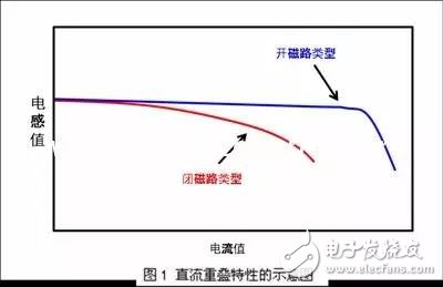
At the same time, the "rated current based on the rate of change of the inductance value" is defined as the rated current of the degree of decrease in the inductance value. When the range is exceeded, the IC control may be unstable due to an increase in ripple current. Further, depending on the magnetic circuit configuration of the inductor, the tendency of magnetic saturation (i.e., the tendency of the inductance value to decrease) is different. Fig. 1 is a schematic view showing changes in inductance values ​​caused by different magnetic circuit configurations. With regard to the open circuit type, as the DC current increases, a relatively flat inductance value appears until the predetermined current value, but the value of the boundary current decreases sharply with the predetermined current value. On the contrary, as the DC current type increases, the value of the permeability decreases gradually, so the inductance value slowly decreases.
The rated current parameter in the power inductor specification only indicates the saturation current Isat value of the medium.
Little common sense: the difference between Isat and rms Isat and Irms are technical terms that our engineers often encounter, but because of some customer problems, they often confuse the two, causing engineering errors. What is Isat and Irms, and what does Chinese mean? How are Isat and Irms defined, and what are they related to? What are we defining in inductor design?
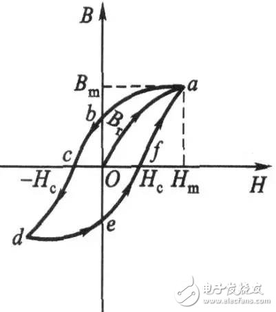
Isat: refers to the saturation current of the magnetic medium. In the BH curve below, it refers to the amount of DC current required for the magnetic medium to reach the Hm corresponding to Bm. For the inductor, that is, the magnitude of the current after the inductance drops to a certain ratio, such as SRI1207- For 4R7M products, the current with a 20% drop in inductance is 8.4A, then Isat=8.4A. Isat calculates the formula as follows:
Let the cross-sectional area be S, the length is l, the magnetic permeability is μ on the iron ring, and the tight coil NåŒ is wound, and the current passing through the coil is I. According to the magnetic circuit law:
Hl/0.4Ï€=NI=0.7958Hl
For the same material and the core H1 of the crucible changes according to the BH curve, but under the same slope, Hl is constant, therefore:
N1*I1=Hl/0.4Ï€=N2*I2
which is:
N1/N2=I2/I1
Irms: refers to the rated current of the application of the inductor product, also known as the temperature rise current, that is, the DC current corresponding to the surface when the product reaches a certain temperature.
The following is a comparison of the current rated current Irat, saturation current Isat, and temperature rise current Irms in the industry by taking the 4.7uH stacked power inductor in the 2520 series as an example.
Stacked power inductor (ferrite high current inductor) parameter comparison table 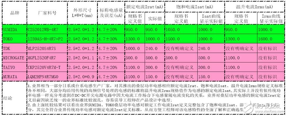
The status quo will mislead engineers to select types and create hidden dangers;
At present, there are quite a few manufacturers of laminated power inductors whose current rating is defined by the rated current rating of the laminated inductor used in traditional signal filtering. The rated operating current is defined according to the temperature rise current of the inductor. In this case, the product design engineer will often measure the rated operating current in the actual circuit according to the traditional power inductor selection experience and the rated current value defined in the supplier's inductance specification, which is likely to cause saturation due to the inductor. The current is lower than the actual operating current of the circuit, and there are hidden dangers as follows:
A). When the inductor is actually working, it will be saturated due to excessive current, causing the inductance to drop too much, causing the current ripple to exceed the maximum allowable specification range of the latter circuit, causing circuit interference, which may not work properly or even be damaged;
B). The actual operating current in the circuit exceeds the saturation current of the inductor, which may cause mechanical or electronic noise due to the decrease in inductance saturation inductance;
C). The actual operating current in the circuit exceeds the saturation current of the inductor, which will cause the inductor to be saturated. The inductance decreases, causing the output voltage & current to be unstable when the power supply is loaded, causing unstable abnormalities such as other unit circuit systems.
D). Inductor rated current (including saturation and temperature rise current) selection of insufficient margin will lead to excessive surface temperature during operation, the overall efficiency is reduced, the acceleration of the inductor itself or the aging of the whole machine to shorten the life.
Guangdong Kaihua Electric Appliance Co., Ltd. , https://www.kaihuacable.com