Optical module classification
According to the package: 1*9, GBIC, SFF, SFP, XFP, SFP+, X2, XENPARK, 300pin, etc.
According to the rate: 155M, 622M, 1.25G, 2.5G, 4.25G, 10G, 40G, etc.
By wavelength: conventional wavelength, CWDM, DWDM, etc.
By mode: single mode fiber (yellow), multimode fiber (orange).
Usability: Hot swap (GBIC, SFP, XFP, XENPAK) and non-hot swap (1*9, SFF).
Package form
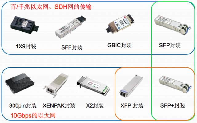
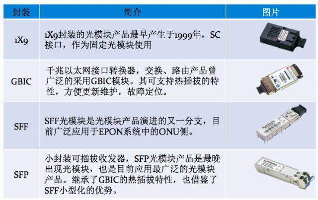
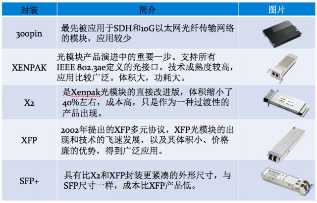
Optical Transceiver (Optical Transceiver)
The optical transceiver module is the core device of optical communication, and performs optical-electrical/electric-optical conversion of the optical signal. It consists of two parts: the receiving part and the transmitting part. The receiving portion realizes the optical-electrical conversion, and the transmitting portion realizes the electro-optical conversion.
Launch section:
An electrical signal input with a certain code rate is processed by an internal driving chip to drive a semiconductor laser (LD) or a light emitting diode (LED) to emit a modulated light signal of a corresponding rate, and an optical power automatic control circuit (APC) is internally provided to output The optical signal power remains stable.
Receiving part:
The optical signal input module of a certain code rate is converted into an electrical signal by the photodetecting diode, and an electrical signal of a corresponding bit rate is outputted through the preamplifier, and the output signal is generally a PECL level. At the same time, an alarm signal is output after the input optical power is less than a certain value.
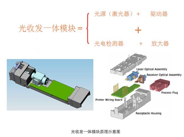
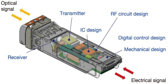
Optical module internal structure
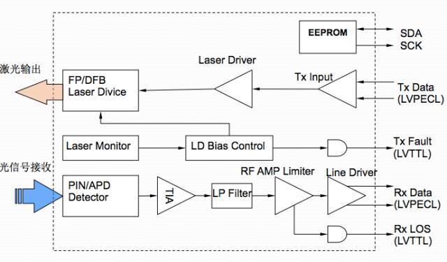
Main parameters of the optical module
Transmission rate
The transmission rate refers to the number of bits transmitted per second in units of Mb/s or Gb/s. Main rates: 100 megahertz, gigabit, 2.5G, 4.25G and 10G.
2. Transmission distance
The transmission distance of the optical module is divided into short distance, medium distance and long distance. It is generally considered that a short distance is 2 km or less, a medium distance of 10 to 20 km, and a long distance of 30 km, 40 km or more.
â– The transmission distance of the optical module is limited, mainly because the optical signal has a certain loss and dispersion when transmitted in the optical fiber.
note:
Loss is the loss of light energy due to the absorption and scattering of the medium and the leakage of light when the light is transmitted in the fiber. This part of the energy is dissipated at a certain rate as the transmission distance increases.
The dispersion is mainly caused by the unequal speed of electromagnetic waves of different wavelengths propagating in the same medium, which causes the different wavelength components of the optical signal to reach the receiving end at different times due to the accumulation of the transmission distance, resulting in pulse broadening, and thus the signal cannot be resolved. value.
Therefore, users need to select appropriate optical modules according to their actual networking conditions to meet different transmission distance requirements.
3. Center wavelength
The center wavelength refers to the optical band used for optical signal transmission. Currently, there are three main wavelengths of optical modules commonly used: the 850 nm band, the 1310 nm band, and the 1550 nm band.
850nm band: mostly used for short distance transmission of ≤2km
1310nm and 1550nm bands: mostly used for medium and long distance transmission, more than 2km transmission.
Fiber type1. Fiber Mode (Fiber Mode)
According to the transmission mode of light in the optical fiber, the optical fiber can be divided into a single mode fiber and a multimode fiber.
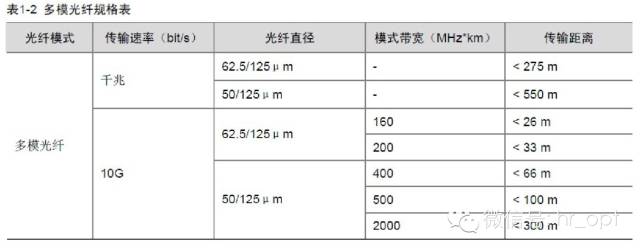
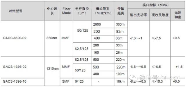
Multimode Fiber (MMF) has a thick core and can transmit multiple modes of light. However, the dispersion between the modes is large, and the dispersion between modes is gradually increased as the transmission distance increases. The transmission distance of multimode fiber is also related to its transmission rate, core diameter and mode bandwidth. For the specific relationship, please refer to the following table.
Single Mode Fiber (SMF) has a fine core and can only transmit one mode of light. Therefore, its inter-mode dispersion is small and suitable for remote communication.
2. End face and diameter of the fiber
Follow the pin end of the fiber connector connector: PC, SPC, UPC, APC
According to the diameter of the fiber connector: Φ3, ​​Φ2, Φ0.9
3. Fiber Interface Connector Type
The interface connector is used to connect the pluggable module and the corresponding transmission medium. The fiber optic connector is an indispensable passive component in the optical fiber communication system. Its use makes the detachable connection between the optical channels possible, which not only facilitates the commissioning and maintenance of the optical system, but also makes the optical system transfer scheduling more convenient. flexible.
According to the type of fiber:
Single mode fiber optic connector (generally G.652 fiber: fiber inner diameter 9um, outer diameter 125um);
Multimode fiber optic connector (one is G.651 fiber with an inner diameter of 50um and an outer diameter of 125um; the other is an inner diameter of 62.5um and an outer diameter of 125um);
According to the connector form of the fiber connector: FC, SC, ST, LC, MU, MTRJ, etc. Currently, FC, SC, ST, LC are commonly used.

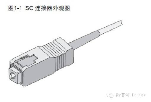
SC (Subscriber Connector Standard Connector), a molded plug-in coupling connector developed by NTT Corporation of Japan. The outer casing is molded by a molded glass fiber plastic and has a rectangular shape; the pins are made of precision ceramics, and the coupling sleeve is a metal slitted casing structure. The fastening method adopts the plug-and-pin type and does not need to be rotated. The appearance is as follows
The LC connector (Lucent Connector or Local Connector) has the following appearance:
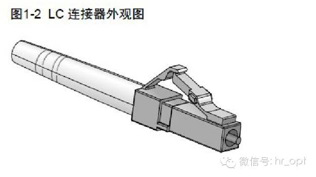
Note: To protect the fiber optic connector, be sure to cover the dust cap when the fiber is not connected.
Interface indicator
Output optical power
The output optical power refers to the output optical power of the light source at the transmitting end of the optical module.
It can be understood as the intensity of light in W or mW or dBm. Where W or mW is a linear unit and dBm is a logarithmic unit. In communication, we usually use dBm to represent optical power.
Formula: P(dBm)=10Log(P/1mW)
The optical power is attenuated by half and reduced by 3dB. The optical power of 0dBm corresponds to 1mW.

Measured using an optical power meter. For the PON product, since the ONU end adopts the burst mode, it needs to use a dedicated optical power meter to measure and serially connect in the line, and can instantly give the current uplink and downlink optical power.
Receiving sensitivity
Receive sensitivity refers to the minimum received optical power of the optical module at a certain rate and bit error rate, in dBm. In general, the higher the rate, the worse the receiving sensitivity, that is, the larger the minimum received optical power, the higher the requirement for the receiving device of the optical module.

Considering the increase in link loss caused by fiber aging or other unpredictable factors, the optimal received optical power range is controlled by 2-3dB above the receiving sensitivity to 2-3dB below the overload point, which is the white area in the above figure.
Pressure sensitivity
The pressure sensitivity refers to the sensitivity value of the input signal measured after the addition of the jitter and vertical eye closure degradation conditions, in dBm. This concept is only for 10G interface modules (XENPAK modules and XFP modules).
Optical module emits optical power and receiving sensitivity
The transmitted light power refers to the light intensity at the transmitting end, and the receiving sensitivity refers to the light intensity that can be detected. Both are in dBm and are important parameters affecting the transmission distance. The distance that an optical module can transmit is mainly limited by both loss and dispersion.
The loss limit can be estimated according to the formula: loss limited distance = (transmitted light power - receive sensitivity) / fiber attenuation.
The amount of fiber attenuation is related to the fiber chosen. Generally, the current G.652 fiber can achieve 0.5dB/km in the 1310nm band and 0.3dB/km in the 1550nm band. The 50um multimode fiber is 2dB/km in the 850nm band 4dB/km 1310nm band. For a 100 megabit, gigabit optical module, the dispersion is much larger than the loss is limited, and can be ignored.
Saturated light power value
It refers to the maximum optical power that can be detected at the receiving end of the optical module, which is usually â€3dBm. When the received optical power is greater than the saturated optical power, the error will also occur. Therefore, for an optical module that emits a large optical power without an attenuation loopback test, an error occurs.
Light saturation
Also known as saturated optical power, it refers to the maximum input optical power when a certain bit error rate (10-10~10-12) is maintained at a certain transmission rate, the unit is: dBm.
It should be noted that the photodetector will have photocurrent saturation under strong light. When this phenomenon occurs, the detector needs a certain time to recover. At this time, the receiving sensitivity decreases, and the received signal may be misjudged. It causes bit error, and it is very easy to damage the receiver detector. In operation, try to avoid exceeding its saturated optical power.
note
For a long-haul optical module, the average output optical power is generally greater than its maximum input optical power (ie, light saturation). Therefore, users should pay attention to the length of the optical fiber used to ensure that the actual received optical power reaching the optical module is less than its optical saturation. Degree, otherwise it may cause damage to the optical module.
SFP optical module
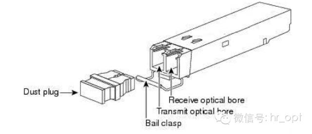
SFP optical module, the full name of the Small Form-factor Pluggable, is a small hot-swappable optical transceiver module. The SFP module is half the size of the GBIC module and can be configured with more than double the number of ports on the same panel. The other functions of the SFP module are basically the same as the GBIC. Some switch manufacturers call the SFP module a miniaturized GBIC (MINI-GBIC).
structure appearance:
classification:
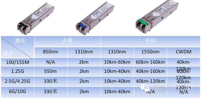
Rate: 155M, 1.25G, 2.5G, 4.25G, etc.
Wavelength: regular wavelength, CWDM, DWDM
Distance: short distance, medium distance, long distance
Transmission mode: electrical port, single mode (fiber yellow), multimode (fiber orange)
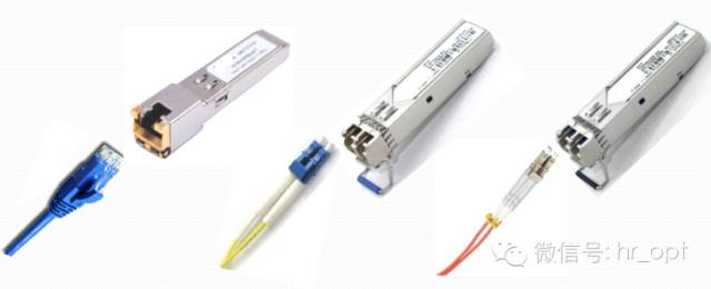
The special types of SFP optical modules include: BIDI-SFP, electrical SFP, CWDM SFP, DWDM SFP, SFP+ optical modules.
BIDI module
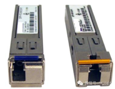
BiDi (Bidirectional): single fiber bidirectional. With WDM technology, different center wavelengths are used for both transmit and receive directions. A two-way optical signal is transmitted by a fiber. A general optical module has two ports, TX is a transmitting port, and RX is a receiving port. The optical module has only one port, which is filtered by a filter in the optical module, and simultaneously performs transmission of a 1310 nm optical signal and reception of a 1550 nm optical signal. Or the opposite. Therefore, the module must be used in pairs, and his biggest advantage is to save fiber resources.
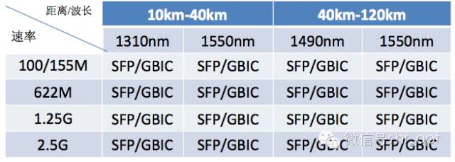
Application areas: regular SFP, xWDM SFP, and PON SFP
C-SFP
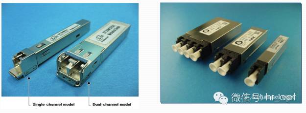
Compact SFP, a compact SFP, is based on the existing SFP package and is developed into a more advanced and compact CSFP package.
Three C-SFPs are defined in the CSFP MSA:
1ch Compact SFP
2ch Compact SFP (Option 1)
2ch Compact SFP (Option 2)
CWDM module
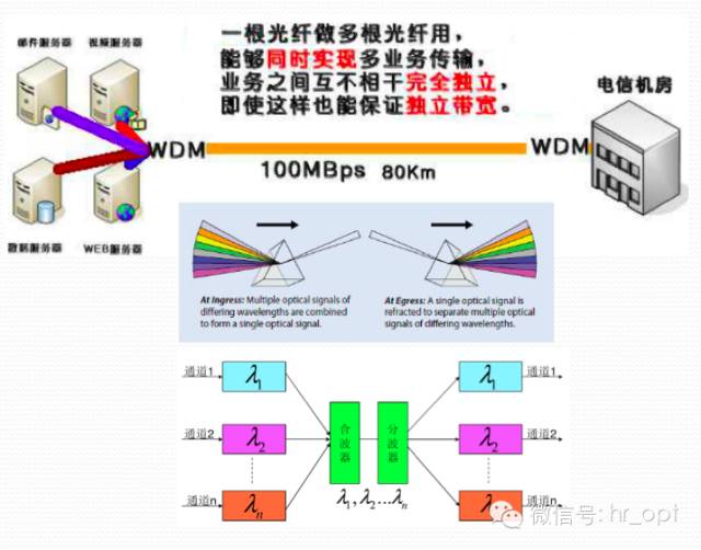
The CWDM optical module adopts CWDM technology, which can combine optical signals of different wavelengths and transmit them through one optical fiber through an external wavelength division multiplexer, thereby saving fiber resources. At the same time, the receiving end needs to decompose the complex optical signal using a wave decomposition multiplexer.
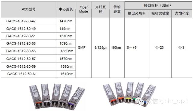
The CWDM SFP optical module is divided into 18 bands, from 1270nm to 1610nm, separated by 20nm between each two bands.
CWDM SFP has speed and protocol transparency. CWDM provides a protocol-transparent transmission channel that provides different rates on a single fiber, allowing users to directly go up and down a certain wavelength without converting the original signal format.
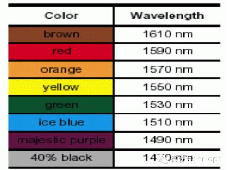
Commonly used 8 bands, from 1470nm to 1610nm, each channel is separated by 20nm.
Colors are often used to distinguish between different band optical modules.
When do I use CWDM SFP?
DWDM module
DWDM SFP is a dense wavelength division multiplexing technology that can couple different wavelengths of light into a single-core fiber for transmission. The channel spacing of the DWDM SFP is 0.4 nm, 0.8 nm, 1.6 nm, etc., and the spacing is small, requiring additional wavelength control devices.
A key advantage of the DWDM SFP is that its protocol and transmission speed are irrelevant.
Electric port module
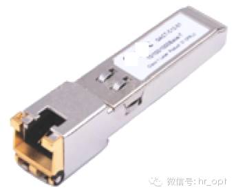

The electrical port module, namely the Copper SFP, the SFP package, and the electrical port module, can support a maximum transmission distance of 100m (RJ45, Category 5 twisted pair is the transmission medium).
SFP+ optical module
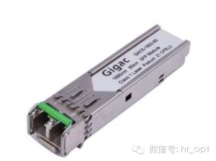
SFP+ optical module: It is a new generation of 10G optical module. It can meet Fibre Channel 8.5G and Ethernet 10G applications according to ANSI T11 protocol.
The SFP+ is about 30% smaller than the previous XFP optical module, which looks the same as a normal SFP optical module.
SFP+ only retains the basic electro-optical and photoelectric conversion functions, which reduces the signal control functions of SerDes, CDR, EDC, MAC, etc. in the original XFP design, which simplifies the design of 10G optical modules and consumes less power.
Significant advantages such as high density, low power consumption, lower system construction cost
SFP+'s shielding requirements are more stringent than SFP and require better shielding.
XFP module
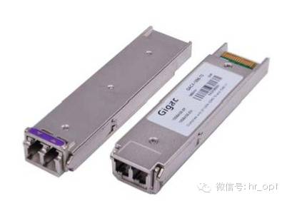

The XFP module is a hot-swappable, small-to-board, serial-serial optical transceiver that supports SONET OC-192, 10 Gbps Ethernet, 10 Gbps Fibre Channel, and G.709 links .
GBIC optical module
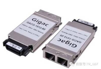
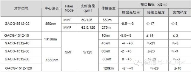
GBIC is an abbreviation of Giga Bitrate Interface Converter, which is an interface device for converting gigabit electrical signals into optical signals. The GBIC is designed for hot swapping and is an interchangeable product that meets international standards.
Xenpak optical module
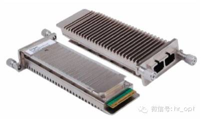

The Xenpak optical module is connected to the board through a 70-pin SFP connector. The data channel is the XAUI interface. Xenpak supports all optical interfaces defined by IEEE 802.3ae and can provide 10.3 Gb/s, 9.95 Gb/s or 4×3.125 on the line side. The rate of Gb/s.
Xpak and X2 optical modules
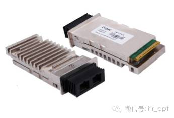
Both Xpak and X2 optical modules have evolved from the Xenpak standard. The internal functional modules are basically the same as Xenpak, and the same applies to the boards. The functions of the 10G Ethernet optical interface can be realized by using one module. Since the Xenpak optical module needs to be slotted on the circuit board when it is mounted on the circuit board, the implementation is complicated and high-density applications cannot be realized. The Xpak and X2 optical modules have been modified to be about half the size of Xenpak and can be placed directly on the board, making them suitable for high-density rack systems and PCI NIC applications.
SFP optical module selectionThe transmission distance of the optical module is divided into short distance, medium distance and long distance. The nominal transmission distance of the module model is only used as a classification method, and it cannot be directly applied in practical applications. Because the optical signal has a certain loss and dispersion when transmitted in the optical fiber, the nominal transmission distance cannot be achieved.
Loss is the loss of light energy due to the absorption and scattering of the medium and the leakage of light when the light is transmitted in the fiber. This part of the energy is dissipated at a certain rate as the transmission distance increases.
The dispersion is mainly caused by the unequal speed of electromagnetic waves of different wavelengths propagating in the same medium, which causes the different wavelength components of the optical signal to reach the receiving end at different times due to the accumulation of the transmission distance, resulting in pulse broadening, and thus the signal cannot be resolved. value.
Therefore, users need to select appropriate optical modules according to their actual networking conditions to meet different transmission distance requirements. The actual transmission distance depends on the actual transmit power of the corresponding model optical module, the transmission attenuation on the optical path, and the receiving sensitivity of the optical port.
The transmitted optical power and receiving sensitivity are important parameters that affect the transmission distance.
The loss limit can be estimated according to the formula:
Loss limited distance = (transmitted light power - receiving sensitivity) / fiber attenuation
The amount of fiber attenuation is related to the actual fiber selected:
G.652 fiber can do:
13dBnm band 0.5dB/km
1550nm band 0.25dB/km
50um multimode fiber:
850nm band 3.5dB/km
2dB/km in the 1310nm band.
For long-haul optical modules: average output optical power > saturated optical power
Pay attention to the length of the optical fiber to ensure that the actual received optical power of the optical module is less than its optical saturation. Otherwise, the optical module may be damaged.
SFP optical module installation
SFP optical module installation
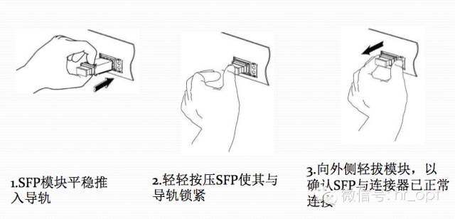
SFP optical module unloading
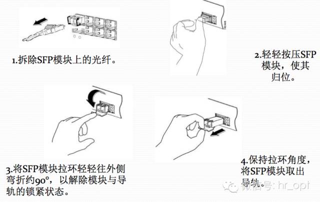
Note: Never let the end of the fiber face your eyes. Never look inside the fiber. Do not look at the fiber tail directly or with the instrument. The laser is invisible, but it can cause permanent damage to the human eye.
Optical module function failure important reason
The failure of the optical module function is divided into the failure of the transmitting end and the failure of the receiving end. The specific causes are analyzed. The most frequently occurring problems are concentrated in the following aspects:
1. Optical port pollution and damage
The optical link loss becomes large due to pollution and damage of the optical interface, resulting in no optical link. The reasons for this are:
A. The optical port of the optical module is exposed to the environment, and the optical port is contaminated by dust;
B. The end face of the fiber optic connector used has been contaminated, and the optical module optical port is secondaryly contaminated;
C. The end face of the optical connector with pigtail is improperly used, and the end face is scratched;
D. Use inferior fiber optic connectors;
2. ESD damage
ESD is the abbreviation of ElectroStatic Discharge, which is "electrostatic discharge". It is a very fast process with a rise time of less than 1 ns (1 billionth of a second) or even hundreds of ps (1 ps = 100 billionth of a second). ESD can generate several Strong electromagnetic pulse of ten Kv/m or even larger. Static electricity will absorb dust, change the impedance between the lines, affect the function and life of the product; ESD's instantaneous electric field or current generates heat, which will cause the component to be injured, still work in the short term but the life is affected; even destroy the insulation or conductor of the component, so that The component does not work (completely destroyed). ESD is inevitable. In addition to improving the ESD resistance of electronic components, it is important to use them correctly. The factors that cause ESD damage are:
The environment is dry and easy to produce ESD;
Abnormal operation, such as: non-hot-swappable optical module with live operation; without electrostatic protection, directly touch the electrostatically sensitive pins of the optical module [t2]; there is no anti-static packaging during transportation and storage;
The equipment is not grounded or has poor grounding;
Optical transceiver integrated optical module application note
Optical port problem
Loss attenuation everywhere on the optical link is related to the performance of the transmission, so it is required:
A. Select a fiber optic connector that meets the network access criteria;
B. The fiber optic connector should have a cap. When not in use, cover the cap to avoid contamination of the fiber optic connector and secondary contamination of the optical module optical port; when the cap is not in use, it should be stored in a dustproof and clean place;
C. The fiber connector insertion is a horizontal alignment optical port to avoid scratching the end face and the sleeve;
D. The optical module optical port is protected from prolonged exposure. When not in use, the optical port plug is capped; when the optical port plug is not in use, it is stored in a dustproof and clean place;
E. The end face of the fiber optic connector is kept clean to avoid scratches;
2. ESD damage
ESD is an inevitable phenomenon in nature. Preventing ESD from starting with preventing charge accumulation and allowing charge to discharge quickly:
A. Maintain the humidity of the environment 30~75% RH;
B. Perform electrostatic protection when operating the optical module (such as: with an electrostatic ring or discharge the static electricity through the device in advance), and contact the optical module housing to avoid touching the PIN pin of the optical module.
C. The related equipment used is grounded at the common grounding point of parallel grounding to ensure the shortest grounding path, the minimum grounding loop, and the grounding cannot be connected in series. The design method of connecting the grounding loop with external cables should be avoided;
D. Anti-static packaging and anti-static turnover box/car when packaging and turnover;
E. It is forbidden to perform hot swap operation for non-hot-swappable equipment;
F. Avoid directly detecting static-sensitive pins with a multimeter test pen;
Simple optical module failure judgment step
1. Test whether the optical power is within the requirements of the index, if there is no light or low optical power. Approach:
A. Check the wavelength and unit of measurement (dBm) of optical power selection
B. Clean the end face of the fiber optic connector and the optical port of the optical module.
C. Check the end of the fiber connector for blackening and scratching, whether the fiber connector is broken, and replace the fiber connector for interchangeability test.
D. Check the fiber connector for small bends.
E. The hot-swappable optical module can be re-plugged and tested.
F. Replace the optical module on the same port or replace the port test with the same optical module.
2. The optical power is normal but the link cannot be connected. Check the link light.
SFP optical module related reference standard
INF-8074i: SFP MSA
SFF-8472: Digital Diagnostic Interface Protocol
DWDM MSA SFP: Dense Wavelength Division Multiplexing Module Standard
GR-468-CORE: General Standard for Reliability of Optical Devices
ITU-T G.651: Multimode fiber standard
ITU-T G.652: Single mode fiber standard
21CFR 1040.10 Laser Safety Level
YD/T1352-2005: Gigabit Ethernet Industry Standard
Motor Three-Phase A.C Induction,Ac Motor Electric Motor Induction Motor,Electric Motor Centrifugal Pump,Electric Motor Centrifugal Switch Gear
Ningbo Zhenhai Rongda Electrical Appliance Co., Ltd. , https://www.centrifugalswitch.com