AD8205 is a single-supply high-performance differential amplifier introduced by American Analog Devices. The typical single-supply supply voltage is 5V, and its common-mode voltage input range is -2~65V, and it can withstand input common-mode voltages of -5~+70V. , It is suitable for industrial equipment that detects small differential voltage under high common mode voltage.
Its gain is fixed at 50V/V, operating temperature range is -40~+125°C, offset voltage temperature drift is less than 15μV/°C, gain temperature drift is less than 30ppm/°C (ambient temperature can be as high as 125°C), in the entire specified temperature range It has excellent DC performance and has a common mode rejection ratio of up to 80dB in the frequency band from DC to 100kHz. Therefore, the measurement loop error is small and the accuracy is high. It is very suitable for motor control, transmission control, magnetic levitation control, vehicle power control, fuel injection control, engine management, and DC-DC conversion control systems.
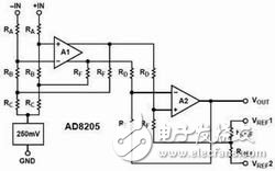
Figure 1 High-side current sensor AD8205 internal circuit principle diagram Internal circuit structure and working principle
The internal circuit of AD8205 consists of two integrated operational amplifiers A1 and A2 and a resistor network, as well as a small reference voltage source and bias circuit. The circuit structure is shown in Figure 1.
The pre-attenuation of A1 is composed of resistors RA, RB, and RC, which can attenuate the common-mode voltage to a suitable input voltage range. Two sets of attenuators form a bridge network with an attenuation rate of 1/16.7. After the input signal is attenuated, the amplitude of the input signal is kept within the power supply voltage range. When the input voltage exceeds the power supply voltage or is lower than the common ground voltage At this time, the internal reference voltage works, so that the amplifier can still work normally when a negative common-mode voltage signal is input. When the bridge is balanced, the differential input signal generated by the common-mode voltage signal is 0V. Of course, the input network also attenuates the input differential voltage signal. Amplifier A1 amplifies the attenuated signal by 26 times, and its input and output are in differential form. In order to obtain the largest AC common-mode rejection ratio. In addition, the resistance matching rate of the resistors RA, RB, RC, RD and RF after laser calibration is better than 0.01%. This high-precision calibration enables the device to obtain a common-mode rejection ratio of more than 80dB.
Amplifier A2 converts the differential signal output by A1 into a single-ended signal and amplifies it by 32.15 times. The reference input terminals VREF1 and VREF2 are both connected to the non-inverting input terminal of A2 through a resistor RREF, so that the output can be adjusted arbitrarily within the required output voltage range. When two reference input terminals are used in parallel, the gain of reference voltage from input to output is 1V/V; when any reference input terminal is used alone, its gain is 0.5V/V. The total gain of AD8205 is attenuated by the attenuation circuit The ratio is 1/16.7, the magnification of A1 is 26, and the magnification of A2 is 32.15. AD8205 has the ability to absorb pull-down current of 300μA, and uses a class A PNP tube to connect to the pull-up resistor output.
Output mode settingUnipolar output
This method is generally used to measure the unidirectional change current flowing through the sampling resistor. There are two basic modes: ground-referenced and V+-referenced output mode. In unipolar operating mode, when the differential input is 0, the output can be biased to the negative (close to ground) or positive peak (V+). When the differential voltage is applied to the input terminal, the output will move in the reverse direction to the peak value. At this time, the input differential voltage amplitude corresponding to the full-scale output is close to 100mV, and its polarity is determined by the static setting of the output voltage. When biased to the positive peak value, the input differential voltage should be negative and the output will drop from the positive peak value; on the contrary, if the static bias is to ground, the input differential voltage should be positive and the output should rise from 0.
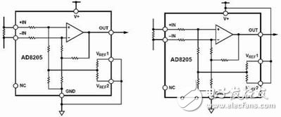
(A) Take ground as reference (b) Take V+ as reference
Figure 2 Unipolar output connection mode
(A) External reference voltage output (b) Separate reference voltage output
Figure 3 Bipolar output connection mode
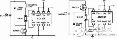
(A) High-side current sensor and low-side switch method (b) High-side current sensor and high-side switch method
Figure 4 Circuit configuration
The ground-referenced output connection is shown in Figure 2(a). Its two reference input terminals are connected to the ground, when the input differential voltage is 0, its output is biased to the inverted peak value (about 0.05V).
The output connection mode with V+ as the reference is shown in Figure 2(b). Its two reference input terminals are connected to the positive power supply. When the input differential voltage is 0, its output is biased to the peak value of the positive phase (about 4.8V).
Bipolar outputWhen bipolar output, AD8205 can measure the bidirectional current flowing through the sampling resistor. At this time, the output can be biased to any position within the output range. When the detected currents in the positive and negative directions are of equal amplitude, the output must be biased to the middle position of the full-scale output. When the bidirectional current amplitude is asymmetrical, the output offset can deviate from the half-scale position correspondingly. Its two reference inputs VREF1 and VREF2 are respectively connected to an internal resistor RREF and then connected to the same internal bias node. The operation modes of these two reference input terminals are exactly the same. Connect the corresponding voltages to the two reference voltage input terminals to complete the output bias. In the bipolar output mode, there are generally the following two connection modes.
1) When the input bidirectional current amplitude is the same, connect the two reference voltage input terminals to the output terminal of an external reference voltage source, as shown in Figure 3(a). When the input voltage is negative with respect to -IN, the output voltage will drop from the reference voltage. Conversely, when the input voltage is positive with respect to -IN, the output voltage will rise from the reference voltage.
2) Connect one of the two reference voltage input terminals to the power supply voltage V+ terminal, and the other reference voltage input terminal to ground, as shown in Figure 3(b). When the input differential voltage is 0, the output voltage is biased to the middle position of the AD8205 power supply voltage. The advantage of this connection is that no external reference source is needed when measuring bidirectional current, and the output will automatically follow the change of the power supply voltage according to the ratio to generate a half-amplitude bias. In other words, regardless of whether the power supply voltage is rising or falling, the output bias point will always remain at the middle of the power supply voltage. For example, when the power supply voltage is 5V, the output will be biased to 2.5V; and when the power supply voltage rises by 10%, the output will be biased to 2.75V.
typical applicationHigh-side current sensor and low-side switch mode
As shown in Figure 4(a), the source of the PWM control switch is connected to the reference ground, and the inductive load and sampling resistor are connected in series between the power supply and the PWM control switch. When the PWM switch is closed, the common-mode voltage on the sampling resistor drops to close to the negative peak value; when the PWM switch is opened, the common-mode voltage generated on the sampling resistor is the sum of the power supply voltage and the forward voltage drop of the freewheeling diode. The advantage of this method is that when the PWM switch is turned off, because the sampling resistor is placed on the high side of the power supply, the sampling resistor is still in the current loop, so that all currents on the load, including the freewheeling current, can still be monitored, and it is easy to identify the Ground short-circuit fault to realize the short-circuit protection of the circuit.
High-side current sensor and high-side switch mode
As shown in Figure 4(b), the PWM switch and sampling resistor are both located on the high side of the voltage. When the PWM switch is turned on, the load power will be removed, but the freewheeling current can still be provided and monitored to achieve current control diagnosis. In the working process, most of the time the power supply is isolated from the load, so that the adverse effects caused by the differential voltage between the load and the ground can be minimized. When the PWM switch is closed, the power supply voltage will be connected to the load, and the common mode voltage will increase to the power supply voltage. When the PWM switch is turned on, the voltage will reverse and pass through the inductive load. Due to the function of the freewheeling diode, the common-mode voltage on the sampling resistor is maintained at a voltage drop lower than the on-state diode of the ground.
Figure 5 Motor control principle diagram
Motor controlAs shown in Figure 5, AD8205 is used as a part of the control loop in the H-bridge motor control circuit. The motor and the sampling resistor are connected in series and placed in the middle of the H-bridge. By detecting the voltage on the sampling resistor, the current motor can be accurately measured. Current and its direction. At this time, the output of AD8205 is set to an external reference bidirectional mode, so that it can measure the bidirectional current of the H-bridge switch and monitor the direction of the motor at the same time. Since the ground is not a particularly stable reference level, taking the ground as a reference will result in inaccuracy of the measurement. Therefore, this test scheme is much better than the test method that uses ground as the reference level.
ConclusionIn a word, the circuit structure that adopts AD8205 to realize the detection of small differential voltage under high common-mode voltage is simple and reliable, and the monitoring accuracy is high. It is especially suitable for power monitoring, hydraulic control, magnetic levitation control and other control systems of 42V automotive systems.
Copper Tube Terminals Without Checking Hole
Our company specializes in the production and sales of all kinds of terminals, copper terminals, nose wire ears, cold pressed terminals, copper joints, but also according to customer requirements for customization and production, our raw materials are produced and sold by ourselves, we have their own raw materials processing plant, high purity T2 copper, quality and quantity, come to me to order it!
Copper Tube Terminals Without Checking Hole,Cable Lugs Insulating Crimp Terminal,Cable Connector Tinned Copper Ring Terminal,Tubular Cable Lugs Crimp Terminal
Taixing Longyi Terminals Co.,Ltd. , https://www.longyicopperlugs.com