CAN bus consists of CAN controller, CAN transceiver, data transmission line, data transmission terminal and other components. The CB311's ECU (engine control unit), TCU (transmission control unit), FEPS (keyless entry and keyless start system), and four instrument clusters are connected via the CAN bus. CAN controllers and CAN transceivers are integrated. Electronic control unit. CB311CAN bus structure shown in Figure 1.
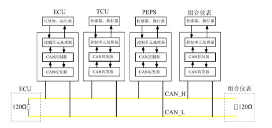
Figure 1 The overall structure of the CB311 CAN bus
1, CAN controllerThe CAN controller is integrated inside the electronic control unit and receives the data transmitted from the microprocessor of the control unit. The CAN controller processes this data and passes it to the CAN transceiver; the same CAN controller also receives the data from the transceiver and passes it to the microprocessor of the control unit after processing.
2, CAH transceiverThe CAN transceiver is integrated inside the electronic control unit and simultaneously has the functions of receiving, transmitting and converting data signals. It converts the level signal data sent from the CAN controller into a voltage signal and sends it out over the data transmission line in a broadcast manner. At the same time, it receives the voltage signal sent by the data transmission line and converts the voltage signal into level signal data and sends it to the CAN controller.
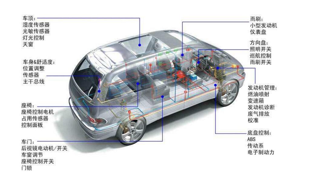
3, data transmission lineIn order to reduce the interference, the data transmission line of the CN bus adopts twisted pair cables with a lay length of 20mm and a cross-sectional area of ​​0.5m. These two lines are called CAN-H and CAN-Low lines (CAN-L). ),as shown in picture 2. The data transmitted on the two wires is the same and the voltage values ​​mirror each other. In this way, the voltage difference between the two wires is kept at a constant value, and the generated electromagnetic field effects will cancel each other out due to the opposite polarity. By this method, the data transmission line can be protected from external radiation; at the same time, when radiated outwards, it is practically neutral (ie, no radiation).
4, data transmission terminalThe data transmission terminal is a resistor that prevents the data from being reflected back at the end of the transmission to destroy the data. Generally, the data transmission terminal is a 120Q resistor. The data transmission terminal of CB311 is two 1202 resistors, which are respectively integrated in BCU and combination meter.
Constitution and Operational Principle of Automotive CAN Bus Data Transmission SystemThe electronic control units of Hyundai Motors mainly include main controllers, engine control systems, suspension control systems, brake antilock control systems (ABs traction control systems, AsR control systems, instrument management systems, fault diagnosis systems, central locking systems). , seat adjustment systems, etc. All these sub-control systems are connected to form a real-time control system, that is, after the instruction is sent out, it must be ensured that the response within a certain period of time, otherwise, there may be a major accident.This requires the car The cAN communication network has a higher baud rate setting.In addition, in the actual operation of the car, a large number of real-time data exchanges are required between many nodes.If all the nodes of the entire car are hung on a cAN network, Many nodes communicate on the cAN bus, and the information management configuration is slightly improper, so it is easy to cause the bus load to be too large, leading to a decrease in the real-time response speed of the system.This is not allowed in the real-time system, so the realities of the nodes on the car After the analysis, according to the requirements of real-time performance of each node, three rates of high, medium, and low speed were designed. In the same CAN communication network, nodes with strict real-time requirements form a high-speed cAN communication network, and other nodes with relatively low real-time requirements form a medium-speed cAN communication network. The remaining nodes with low real-time requirements are composed of low-speed CANs. The communication network is set up and a gateway is set up to connect these three communication networks with different rates to achieve data sharing among all nodes.
The CAN bus system has a CAN controller, an information transceiver, two data transmission terminals, and two data transmission buses. In addition to the data bus, other components are placed inside each control unit. The reasons for the failure of the analysis of the CAN bus system are generally the following three:
1. The fault caused by the car power system: The working voltage of the car electronic control module is generally 10.5-15.0V. If the working voltage provided by the car power system is not normal, some electronic control modules will appear short-term abnormal work. Will cause the whole car CAN bus system to appear the communication to be unsmooth.
2. Link failure of the automotive CAN bus system: When communication lines are short-circuited, open circuited, or the physical properties of the line cause the attenuation or distortion of communication signals, the electronic control units may not work properly, making the CAN bus system unable to work.
3. Node failure of the automotive CAN bus system: The node is an electronic control module in the automotive CAN bus system, so the node failure is the failure of the electronic control module. It includes a software failure that is a defect or conflict in the transmission protocol or software program, which may cause chaos or failure in the communication of the automotive CAN bus system. Such failures generally occur in batches; hardware failures are generally failures of electronic control module chips or integrated circuits. Causes the automotive CAN bus system not to work properly.
Multimeter measurement diagnosis CAN bus method Detailed system overview:This instruction is used to check if the CAN high speed and CAN low speed signal levels on the bus connection are correct.
Test tips:â— Voltage detection (oscilloscope): The precondition for voltage detection is that the battery is connected and the ignition switch is on.
â— Resistance measurement: During resistance measurement, the part to be tested must be de-energized before measurement. To do this, disconnect the vehicle battery. Wait about 3 minutes until all capacitors in the system are discharged.
Differences between data bus K-CAN (body CAN), PT-CAN (drive CAN) and F-CAN (chassis CAN):â— K-CAN: The data transmission rate is about 100 kBit/s. Single line operation is possible.
â— PT-CAN: The data transmission rate is about 500 kBit/s. Single line operation cannot be performed.
â— F-CAN: The data transmission rate is about 500 kBits/s. Can not be single-line operation
Master unit
The main control unit is an active communication party, and the initiative of communication is issued by it. The main control unit controls the bus and controls the communication. The main control unit can send information to the passive bus user (sub-control unit) in the bus system and receive information according to the requirements of the passive user.
Secondary control unit
The secondary control unit is a passive communication user. The secondary control unit is required to receive and send data.
Multi-master unit system
In a multi-master system, all communication users can assume the role of a master control unit or sub-control unit at a certain time.
Oscilloscope measurement
To find out if the CAN bus is working properly, you must observe the communication on the bus. In this case there is no need to analyze a single bit but only to see if the CAN bus is working. Oscilloscope measurement description: 'CAN bus is likely to work without failure'.
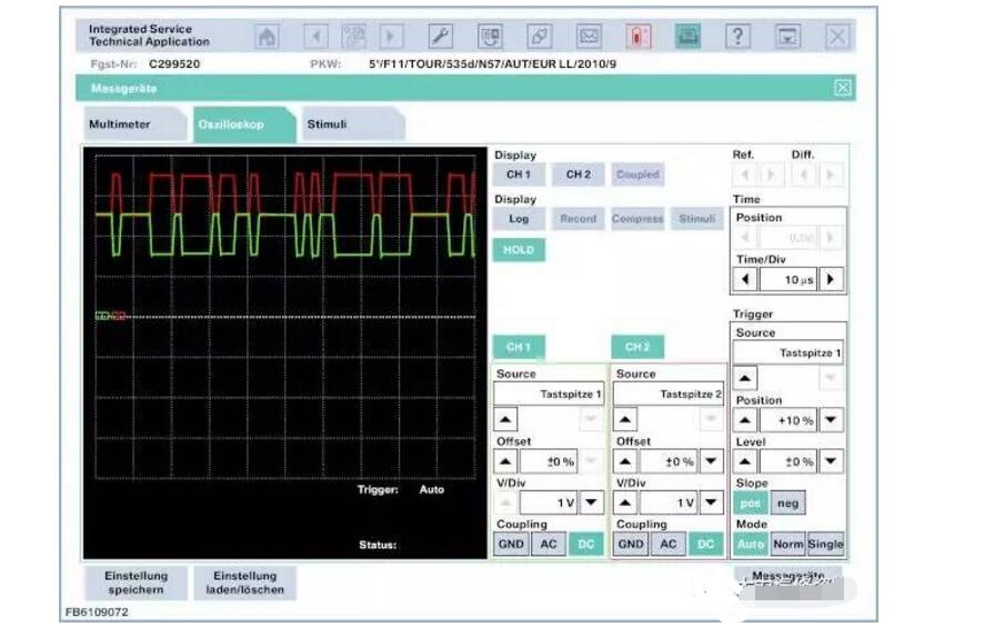
If you use an oscilloscope to measure the voltage between the CAN low (or CAN high) wire and ground, you get a square-wave signal that is within the following voltage limits:
K-CAN:
CAN Low to ground: U min = 1 V, U max = 5 V
CAN High to ground: U min = 0 V, U max = 4 V
These values ​​are approximate and may have several 100 mV deviations depending on the load on the bus
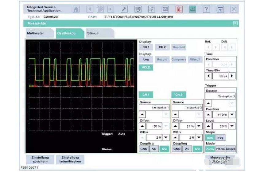
Measure K-CAN: CH1 CAN low, CH2 CAN high
If you use an oscilloscope to measure the voltage between the CAN low (or CAN high) wire and ground, you get a square-wave signal that is within the following voltage limits:
PT-CAN and F-CAN:
CAN Low to ground: U min = 1.5 V, U max = 2.5 V
CAN High to Ground: U Min = 2.5 V, U Max = 3.5 V
Measurement PT-CAN: CH1 CAN low, CH2 CAN high
Bus measurement measurement prerequisites:â— The CAN bus must be powered off.
â— No other meter (parallel meter) is allowed.
â— Measurements are made between the CAN-Low wire and the CAN-High wire.
â— The actual value allows a deviation of several ohms from the standard value.
K-CAN:Because the resistance changes according to the switching logic inside the control unit, the specified resistance measurement cannot be performed on the K-CAN bus!
PT-CAN, F-CAN:To avoid signal reflections, connect a 120 Ω terminating resistor to each of the two CAN bus users (the farthest distance in the PT-CAN network). The two termination resistors are connected in parallel and form an equivalent resistance of 60 Ω. This equivalent resistance can be measured between the data lines after the supply voltage is turned off. In addition, a single resistor can be measured separately.
Prompt measurement with 60 Ω equivalent resistance: A dismantled control unit is disconnected from the bus. Then measure the resistance between CAN-Low wire and CAN-High wire on the plug.
prompt:
Not all vehicles have a terminating resistor on the CAN bus. It can be checked according to the corresponding circuit diagram whether a terminating resistor is installed on the connected vehicle.
CAN bus failureWhen the K-CAN or PT-CAN data bus fails, there may be a short circuit or open circuit on the CAN-Low or CAN-High wire. Or a control unit is damaged.
In order to find the cause of the fault, the following work steps are recommended:
â— Unplug the bus user from the CAN bus until you find the cause of the fault (= control unit X).
â— Check whether the wire leading to the control unit X is short-circuited or open circuited.
â— If possible, test the control unit X.
â— If a branch of the control unit to the CAN bus is short-circuited, only this work step is successful. If one of the wires in the CAN bus is shorted by itself, the wiring harness must be checked.
CSRME safety controller is developed for standard GB27607. By monitoring machine tool safety related equipment, the security of machine control system can meet the requirements of GB27607, and its security meets the requirements of ISO13849-1 (PLe) and IEC61508 (SIL3).
With rich interfaces, CSRME has limited programmable function. It can simultaneously replace many different types of safety control modules or safety PLCs, thus greatly simplifying the safety design of machine control systems and reducing cost.
Safety Controller,Modular Safety Controller,Safety Controller,Electrical Safety Controller,Programmable Logic Controller,Banner Safety Controller
Jining KeLi Photoelectronic Industrial Co.,Ltd , https://www.sdkelien.com