The Voltage Regulator Module (VRM) features low-voltage high-current output, fast load change response, and high output stability. It is mainly used for power supply of integrated circuit chips with special requirements for power supply such as CPU. However, with the rapid development of integrated circuit technology, the transistor volume is rapidly reduced, and the number of single-chip transistors is rapidly increasing. The development trend of such semiconductor manufacturing technology has made the supply voltage of integrated circuit chips lower and lower, the load current is getting larger and larger, and the load change speed is getting faster and faster, and the amplitude is getting larger and larger. Increasingly stringent power requirements for integrated circuit chips require new improvements in the performance of VRM. At the same time, the improvement of performance requires new developments and changes in traditional control methods.
Traditional analog controllers have typically adopted dual closed-loop control since the introduction of the UC1842 series by Unitrode. In this controller, a certain triangular wave signal is required as the peak current control mode, or the V2 control mode controls the inner loop input signal. Therefore, under such a control law, the current ripple of the output filter inductor or the voltage ripple of the output filter capacitor is generally used as the feedback signal of the controller inner loop. However, the current ripple signal of the output filter inductor is used as the controller input to make the controller unable to directly obtain the load current signal. Therefore, this method has an inherent response delay problem in the sampling process. The voltage ripple signal of the output filter capacitor is used as the feedback input signal of the controller, although the feedback speed of the load change can be accelerated. However, as the supply voltage of the integrated circuit continues to decrease, the ripple requirement on the output voltage of the power supply is continuously increased, and the output voltage ripple must be smaller and smaller. Therefore, the voltage ripple of the output filter capacitor is inevitably weaker as the feedback signal of the controller, the signal-to-noise ratio is getting lower and lower, and it is more and more susceptible to external interference. Therefore, the traditional double closed-loop control law has certain defects, and at the same time, this defect has become increasingly unable to adapt to the development of power supply requirements of the integrated circuit industry. Switching power supplies are a very typical nonlinear system and cannot be built with accurate models. At the same time, the fuzzy PID double-closed loop controller is used. As a kind of excellent linear and nonlinear control, the control method is robust and does not need to accurately model the control object.
In this paper, based on Buck converter, a fuzzy PID (F-PID) control method based on output voltage and output current for double closed loop control is proposed. The joint control method of Matlab/Simulink and Cadence PSpice verifies that the new control method has good stability and transient response performance.
Design and implementation of a double closed-loop F-PID controller
The control method proposed in this paper directly controls the duty cycle output value of the controller directly with the load current as the feedback amount, thus avoiding the problems caused by the position of the current sampling point of the conventional controller.
Matlab is the leading control algorithm design simulation tool, especially including Fuzzy Control Toolbox and Simulink design simulation tool. Therefore, Matlab is used as the design simulation tool for the controller part of the control system.
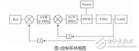
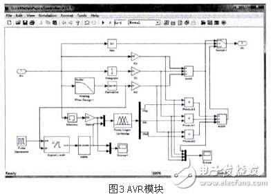
The SimuLink block diagram of this controller is shown in Figure 2. The output voltage is calibrated as the feedback amount of the outer loop to stabilize the output voltage, and the output current is calibrated as the feedback amount of the inner loop to accelerate the load change response. The outer loop voltage controller, the AVR, uses the F-PID controller and the inner loop current controller ACR uses the traditional PID controller to achieve a compromise between controller complexity and performance. The output of the ACR is PWM modulated and used as the drive signal for the Buck converter MOSFET.

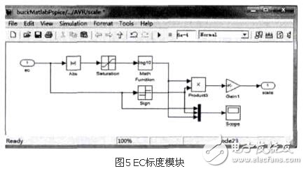
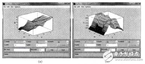
In order to meet the high requirements of VRM for output voltage accuracy, this controller allows the F-PID controller to operate at a small voltage range to improve the output voltage accuracy. The AVR adopts a structure in which the dual controllers of the F-PID and the conventional PID are switched to each other, as shown in FIG. The traditional PID controller controls when the output voltage error is very large, and the F-PID controller controls when the output voltage error is within a certain limit. The fuzzy controller in the F-PID controller uses a typical two-input three-output design, as shown in Figure 4. The input quantity is voltage error E and voltage error change rate EC. The output quantity is the KP, KI, KD adjustment coefficient KKP, KKI, KKD of the traditional PID controller respectively. This can make the fuzzy controller adaptive PID parameter setting. Values, without having to adjust the parameters together. The direct error change rate obtained by directly differentiating the output voltage of the converter is highly susceptible to external disturbances, and the direct error rate varies greatly to plus or minus 1e13. Therefore, this problem does not use the direct error rate of change obtained by differential as the fuzzy controller EC input signal, but instead adopts the method of taking the common logarithm and keeping the original positive and negative, as shown in Figure 5. Adding a low-pass filter before differentiation and adding a first-order sample-and-hold after differentiation to filter out excessive spikes weakens and eliminates the effects of interference.
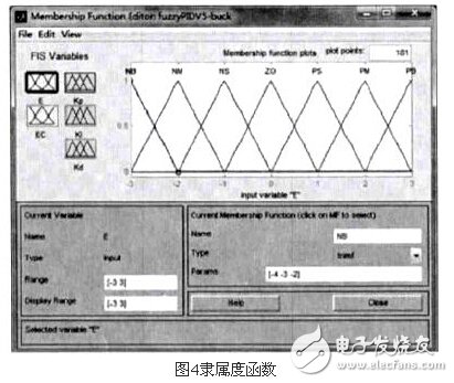
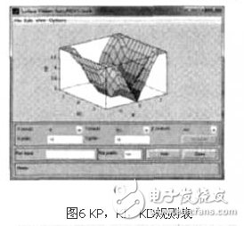
The fuzzy controller uses the Mamdani type. The membership functions of input and output variables are linear, and the fuzzy subsets are {NB, NM, NS, ZE, PS, PM, PB}. The elements in the subset represent negative, negative, negative, zero, and small. , center, Zhengda. The domain of input is [-3, 3], and the domain of output is [0, 6]. The rule table of fuzzy control is shown in Fig. 6.
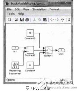
The ACR uses a conventional PID controller to respond quickly to changes in output current, as shown in Figure 7. In the PWM modulation, the output duty ratio at the steady state is set by adjusting the range of the sawtooth wave size to accelerate the stability.
2 Co-simulation of Buck converter and controller
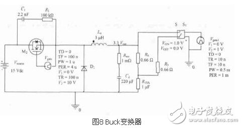
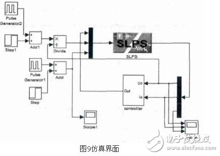
Cadence/Pspice is one of the most commonly used power circuit simulation environments, and it provides an extremely convenient interface for co-simulation with Matlab, the SLPS module in Matlab / Simulink. Therefore, the design and simulation of the Buck transform in this control system are performed in the Pspice environment. The simulation uses a 14~22 V DC input 3.3 V/(0~10 A) DC output as the input and output index of the Buck converter, where Lo=30μH and Co=220μF, as shown in Figure 8 and Figure 9.
3 simulation results
This test was performed to test the performance of the controller in the case where the resistance, current load is fully loaded and half-load to full load step change and the input voltage jumps from the rated minimum step to the maximum value under various load types. .
The Buck converter controlled by the dual closed-loop fuzzy PID controller has very limited effect on the output voltage during any normal load or input change. When the input terminal jumps from the rated minimum input voltage to the rated maximum input voltage, that is, 57% change, the 3.3 V output voltage of the Buck converter changes by about 1%.
For Vivo Oca,Vivo Oca Sheet,Oca Sheet For Vivo Brand,Vivo X90 Oca Sheet Paper
Dongguan Jili Electronic Technology Co., Ltd. , https://www.jlglassoca.com