Radio frequency identification (RFID) technology is used in a wide range of applications. Due to its non-contact and non-line-of-sight features, RFID is particularly well-suited for supply chain management. Passive RFID has been on the market for low frequency (125 kHz) and high frequency (13.56 MHz) for some time. Prior to 2003, a variety of UHF RFID standards have emerged. The Massachusetts InsTtute of Technology's Auto-ID Center (Cambridge, MA) is aware of the challenges of multiple patented RFID standards, recognizing that local protocols can prevent the development and popularity of RFID technology. In order to create regulations for interoperability and international compliance, a single, open standard is required. The next-generation UHF RFID they recommend, the predecessor of the Gen 2 standard, has two meanings. Once a single international standard is established, UHF RFID-based systems will be faster, easier to use, cheaper, and more robust; multi-vendor channels will emerge. The Car Identification Center proposed the launch of Gen 2 at a seminar in Zurich, Switzerland, in June 2003. They eventually converted the work of developing and commercializing the standard into EPCglobal, which was approved in December 2004 as the "860 MHz to 960 MHz second generation UHF RFID communication protocol."
From the perspective of RFID IC design, RFID has two main design constraints: power availability/bandwidth and transponder complexity. Passive UHF RFID transponder design requirements compromise the power requirements, complexity and chip size to achieve the desired performance.
At present, the requirements for spectrum allocation, bandwidth and radiated power of the UHF Industrial, Scientific and Medical (ISM) bands vary widely in some major countries. (Radiation power is often defined as effective isotropic radiated power (EIRP)). According to the "EPC Global" standard, the UHF band ranges from 860 MHz to 960 MHz with an allowable power level of 4W. However, the requirements for the UHFISM band vary from region to region: in North America, the UHF ISM band is 902 MHz to 928 MHz with a maximum EIRP of 4 W; in Europe, the UHF ISM band is 865 MHz to 868 MHz with a maximum EIRP of 2 W; in Japan, UHF ISM The frequency band is 952MHz to 954 MHz and the maximum EIRP is 4W.
The complexity of the transponder is another design constraint. The receiving range of the transponder depends on the lowest conduction power (threshold power) of the RF IC chip (tag). In UHF RFID systems, the principle of passive backscattering is often used in the reverse link from the tag to the reader. The readable range is often determined by the available radiated power of the tag in the forward link from the card reader to the tag because the available backscattered signal strength to the reader RF front end is approximately -25 to -65 dBm.

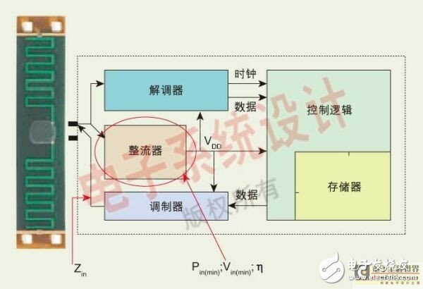
Figure 1: The basic UHF RFID transponder consists of a rectifier, a modulator, a demodulator, and digital circuitry that handles logic level protocol and memory functions.
How to choose the right process to manufacture RFID transponder chips is also a challenge. To meet low power requirements, Schottky point contact diodes with low turn-on voltage, low junction capacitance, and large drive current are typically used. Because the process of producing Schottky contacts is not part of the standard silicon CMOS semiconductor process, Schottky contacts are being investigated for use in standard (low cost) digital bulk CMOS processes. Research on more expensive processes is also underway, such as silicon BiCMOS, which can manufacture high-speed bipolar junction transistor (BJT) devices, and silicon-on-insulator (SOI) technology, which has excellent low-power performance. The key RF circuit technologies required to design a basic UHF RFID transponder are discussed below, including key modules such as rectifiers, modulators/demodulators, and digital blocks.
Rectifier circuit of RFID transponderThe UHF RFID transponder consists of four building blocks: a rectifier, a modulator, a demodulator, and a digital circuit that handles logic level protocol and memory functions (Figure 1). In passive RFID systems, energy is taken from the incident interrogation wave. Since the energy of the interrogation wave is small, it is critical to keep the power of the transponder at a minimum.
The passive RFID transponder utilizes a rectifier circuit to convert the coupled electromagnetic wave power into a DC voltage required by the chip. The parameters describing the performance of the rectifier circuit include the input impedance Zin or the quality factor (Q) of the chip, the operating power Pin of the chip, and the voltage Vin. The rectifier circuit must be capable of converting incident RF energy to DC energy at maximum efficiency (η). Circuit design engineers must achieve maximum output voltage and input impedance while maintaining high conversion efficiency. Common full-wave rectifiers and Dickson charge pumps are two common rectification structures.
Full-wave rectifiers with two diode cascades are common. There are also variations of this structure, including some based on NMOS and PMOS switches. The main thing is that the full-wave rectifier is very efficient. However, full-wave rectifiers require an input voltage of more than 3 VTH so that the chip can output the desired output voltage. Therefore, the full-wave rectifier circuit has a limited range of operation in UHF RFID applications unless it has a high-radiation-resistance antenna and a high-Q matching network to amplify the input voltage. The Q value of the matching network is generally only 10 orders of magnitude.

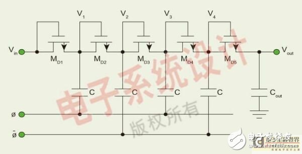
Figure 2: The Dickson charge pump is an optional structure for the UHF RFID rectifier circuit. The figure shows the operation of the Dickson charge pump.
Another optional structure for UHF RFID rectifier circuits is the Dickson charge pump (Figure 2), which is primarily used in non-volatile memories to generate the high programming voltages required for EEPROM circuits. Because most RFID chips also include non-volatile memory, designers can reuse this circuit topology to achieve high voltage circuits, saving development time.
The simplified equation for the Dickson structure is given in Equation 1.

Among them, Vp, RF = input RF signal amplitude, Vf, D = diode forward voltage drop.
Dickson charge pumps can be built with almost any semiconductor device, but with Schottky diodes and low threshold voltage (VTH) MOSFETs designed for optimum performance. The Dickson charge pump circuit requires a small input voltage, and the designer can control the desired output voltage and input impedance by controlling the number of stages (N). However, Dickson charge pumps have lower power conversion efficiency due to the large number of rectifying devices and leakage current and parasitic parameters.
We focus on retro Bluetooth speakers,It has high energy density, mini size, light weight and diversified shapes;Excellent fast charging performance, support fast charging and other excellent features
with a brand-new design, showing retro nostalgia without losing fashion. It uses a 2.5-inch speaker and has many functions such as FM radio, Bluetooth fast connection, multi-mode switching, and HIFI high fidelity. Wireless Bluetooth 4-10 hours of playback (at 50% volume), which adds to its unique charm.
The wireless Bluetooth Speaker supports the function bluetooth player/U disk/TF card/auxiliary player/hands-free call.
TWS can be connected in series. After the two wireless speaker are turned on, press one of Bluetooth speaker the[ M "button and hold for 3 seconds. The two speaker will be automatically paired, and then search for Bluetooth to connect to from phone.
Waterproof Stereo Earphones in-Ear,Ultra-Light earbuds,Portable Vintage speaker,Rechargeable Vintage speaker
Shenzhen Focras Technology Co.,Ltd , https://www.focrass.com