When we design the board, we often pay attention to those parts that seem to be more core and more critical. We may not pay enough attention to those corners and corners, but these places often bring catastrophic consequences.
For example, for the power-on sequence of the power supply, we need to pay attention to the rise time of the system power supply. Many people do not understand that the power is turned on when it is powered on. Why must the rise time be specified? Let me tell you, if this is not handled well, the problem will be big.
Here is an example:
Many simple MCU-based products use the following methods to reset. Is this OK? Of course you can, why? Because so many products have done this, and I have not heard of any problems, of course it is OK.
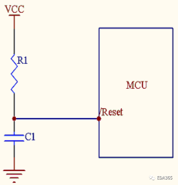
Today we will use the simplest way to describe whether this will be a problem.
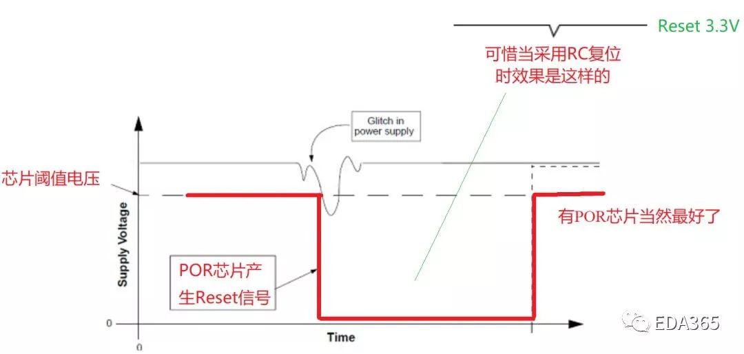
First, let's look at what a power-on reset looks like in an ideal situation:
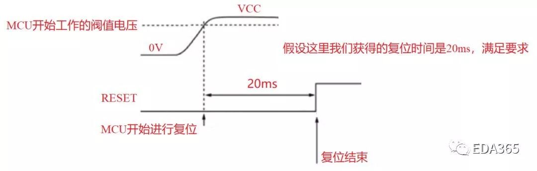
When VCC reaches the working voltage threshold of the MCU, the MCU starts to work, and the reset signal is pulled high after 20ms, Perfect! The problem is that there is always a distance between reality and ideal. Let's first take a look at what kind of waveform will be obtained by using the reset method of RC charging in the above figure:
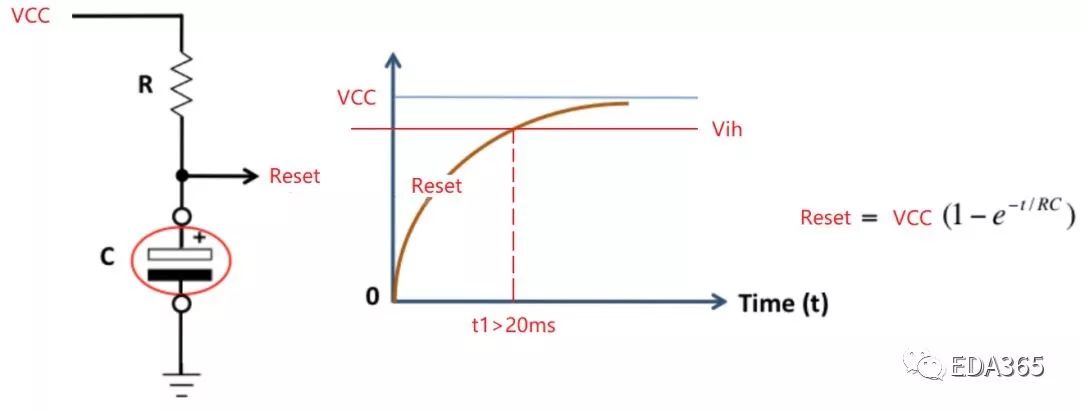
We can see that even when VCC is powered up perfectly, we need to make sure that when Reset is charged to Vih, the time is greater than 20ms, but is this really the case?
It is a pity that there is still a little distance between ideal and reality. Please see the above picture. From VCC power-on to the working voltage threshold, to Reset slowly charging to reach Vih, this period of time is the reset time we need, but this situation is actually very fragile. , what if there is a step or barb on the rising edge of VCC? Haha, the first question arises:
1. The reset time becomes shorter
We can see that when VCC is powered on, after reaching the threshold voltage for the first time, the chip has already started to work, that is, it has started to reset. The second time VCC rises to the threshold voltage, it can be seen that the reset time is shortened, because each chip has a requirement for the reset time. Again, sometimes it gets up, sometimes it doesn't, and it can be worse for high and low temperature tests.
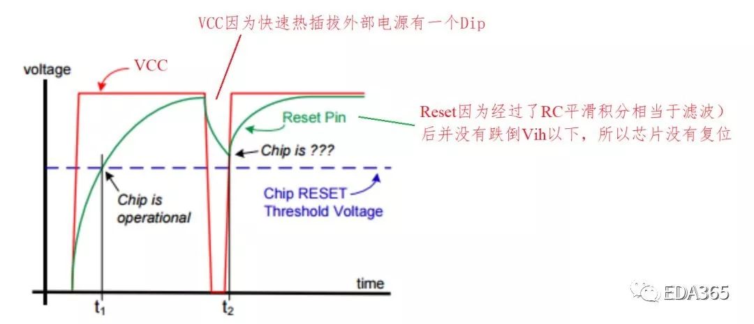
2. Fast hot swap
When the user quickly unplugs and then plugs in the power supply, there will be a drop on VCC, but this drop does not get a deep enough drop on Reset due to the smoothing effect of the RC RC, because the drop of VCC has messed up the inside of the MCU , but the reset signal does not work, the chip will generate lock out or latch up.
In the process of using the product, a very common phenomenon is that many people will quickly plug and unplug the power supply, and the result is that they cannot get up. Only by unplugging the power supply again, and then plugging it in again after a while.
The problem caused by this fast hot-swap caused I2Cexpander lockout on the ASR*** series routers of my original company C. This problem appeared on the products that have been sold, and the software could not solve it, so the consequences were very serious. Yes, as for why EVT has not been tested, this is understandable, because only when there are more samples, will there be stories of all kinds of birds in the forest.
3. Glitch appears on the power supply
In this case, during the working process of the system, if there is external interference or the power supply is too bad, Glitch will sometimes appear on the VCC. At this time, if there is a special POR chip to trigger Reset, then of course there is no problem. Unfortunately, we use a Resistor The Reset method of RC.
Due to the short Glitch time on the power supply, the reset signal drop after RC integration becomes smaller, and it is not small enough to trigger a reset (this is the same as the above fast hot-swap principle), so it is obvious that the system will crash and crash. After that, you can only plug in and unplug the power supply, and you cannot quickly plug and unplug to return to normal.
In order to prove that I am not talking nonsense, I am excerpting a passage from Howard Johnson, a great man, and please read it carefully.
Power interruptions drive power-on-reset circuits crazy. Consider what a power dropout does to the circuit in Figure 1. Imagine that the RC time constant in this figure is 1 sec. Let VCC come up and stabilize at full voltage for perhaps 10 sec .
Next, apply an ac power interruption just long enough to drop VCC to 0V for about 100 msec. If a processor is involved, the dropout is long enough to make scrambled eggs of the processor's internal state machines but not long enough to discharge the RC circuit .If the RC circuit doesn't discharge, ~RESET doesn't activate, and the processor spins out of control, powered on, but lost in space.
4. The power-on sequence is destroyed
Some people here can't figure it out, what does it have to do with the power-on sequence when I power on slowly, please listen to my illustrated explanation as follows:
The power-on sequence requirements of the MCU are as follows: 5V -> 1.8V->3.3V -> Reset.
When the following two situations occur on 5V, problems will arise (in fact, when the USB 5V power supply is used, the power quality of some products is very poor, and we cannot predict the situation of 5V output).
1) 5V has steps or back grooves when powered on
2) 5V has Dip or Glitch during operation
We saw that due to the rapid drop of 5V power supply, 1.8V due to heavy load and large current, quickly discharged and dropped to 0V, and 3.3V due to light load, it was too late to discharge, and the drop was very small, so the power-on sequence became 3.3V = Reset->5V->1.8V, there are two problems:
1) After re-powering on, because 3.3V is always on, it becomes 3.3V first, which is reversed from the first power-on requirement of 1.8V, the result is very simple, the chip is easy to latchup , can't get up, or burn out
2) Due to the 3.3V RC reset used, this time, because 3.3V was too late to discharge, the Reset signal did not respond at all. You think that the power supply of the CPU core has been dropped, and the system has no reset signal. This is too unreasonable, right? Not only is the chip unable to get up, but it is also very dangerous.
To sum up, when we use RC to generate Reset in a simple MCU system, we need to evaluate the risk, and it is OK for the power output quality to be good, and there will be no products that customers frequently hot-plug. On the other hand, if it is some peripheral devices that customers often plug and play, you should choose your R and C values ​​carefully. On the basis of satisfying the reset time, keep them as short as possible. The longer it is, the less safe it is. The power circuit ensures there are no steps, barbs, and too long rise times.
Sometimes when hardware engineers do schematic design, there are many reference designs that can be copied. The problem is that we need to know why when copying other people's schematics, and there is no technical content that cannot be copied, so that we can make progress.
Super High Voltage Film Capacitor
Polyester Film Capacitor,DC Filter Capacitor,Precision Capacitor
XIAN STATE IMPORT & EXPORT CORP. , https://www.shvcomponents.com