The input circuit of the switching power supply mostly uses a rectification plus capacitance filter circuit. At the moment when the input circuit is closed, a large instantaneous inrush current is formed due to the initial voltage on the capacitor (as shown in Figure 1). Especially for high-power switching power supplies, the input uses a larger-capacity filter capacitor. Current can reach more than 100A. Such a large amplitude of the inrush current at the moment of power-on will often cause the input fuse to blow, and sometimes even burn the contacts of the closing switch, and the light will not close the air switch. The above reasons will be The switching power supply is not working properly. For this reason, almost all switching power supplies are provided with soft start circuits for preventing inrush current in their input circuits to ensure normal and reliable operation of the switching power supply. This article describes several common soft-start circuits.
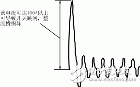
Figure 1 Closing instantaneous filter capacitor current waveform
(1) Using a power thermistor circuit
The thermistor anti-shock current circuit is shown in Figure 2. It utilizes the negative temperature coefficient characteristic of Rt of the thermistor. When the power is turned on, the resistance of the thermistor is large, which limits the impact current; when the thermistor flows through a large current, the resistance heats up. The resistance value becomes smaller and the circuit is in normal working condition. The use of thermistor to prevent the inrush current is generally applicable to the low-power switching power supply. Due to the thermal inertia of the thermistor, it takes time to restore the high-resistance again. Therefore, it is necessary to quickly turn on the power after the power is cut off, sometimes it is not limited. Flow effect.
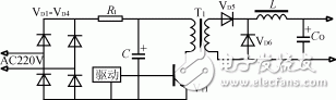
Figure 2 uses a thermistor circuit
(2) Adopt SCR-R circuit
This circuit is shown in Figure 3. When the power supply is momentarily turned on, the input voltage charges the capacitor C via the rectifier bridges VD1 to VD4 and the current limiting resistor R. When the capacitor C is charged to about 80% of the rated voltage, the inverter works normally, and the trigger signal of the thyristor is generated by the auxiliary winding of the main transformer, the thyristor is turned on and the current limiting resistor R is short-circuited, and the switching power supply is in a normal running state.
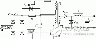
Figure 3 uses the SCR-R circuit
This current limiting circuit has the following problems: after the power supply is momentarily powered off, since the voltage on the capacitor C cannot be abruptly changed, there is still a charging voltage before the power is turned off, and the inverter may still be in operation, keeping the thyristor on. At this time, if the input power is turned back on immediately, the effect of preventing the inrush current will not be achieved.
(3) SCR-R circuit with power failure detection
This circuit is shown in Figure 4. It is the improved circuit of Figure 3, VD5, VD6, VT1, RB, CB constitute the instantaneous power-off detection circuit, the time constant RBCB should be selected slightly larger than half a cycle, when the input instantaneous power-off, the detection circuit is detected The signal turns off the driving signal of the inverter power switch tube VT2, stops the inverter, and cuts off the gate trigger signal of the thyristor SCR to ensure the inrush current is prevented when the power is turned on again.
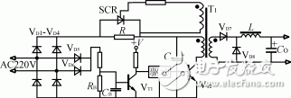
Figure 4 SCR-R circuit with power failure detection
Voltmeter Display,Mini Voltmeter Display,Digital Panel Voltmeter,Voltmeter Lcd
Dongguan Andu Electronic Co., Ltd. , https://www.idoconnector.com