The eighth chapter is to understand AMetal in depth . The content of this article is 8.3 buzzer interface and 8.4 temperature acquisition interface.
8.3 Buzzer interface
> > > 8.3.1 Defining interfaces
1. Interface naming
Since the object of the operation is a buzzer, the interface name is prefixed with "am_buzzer_". For the buzzer, the basic operation is to turn the buzzer on and off, and the corresponding two interfaces can be defined as:
Am_buzzer_on
Am_buzzer_off
In particular, in some applications, an operation similar to the buzzer "click" is required, that is, the beep automatically stops after a certain period of time. You can define its interface name:
Am_buzzer_beep
Am_buzzer_beep_async
There are two interfaces defined here, all of which are used for the buzzer to call the specified time. The difference between the two is that the timing of the function return is different. Am_buzzer_beep will wait for the tweet to end and return. am_buzzer_beep_async will not wait, the function will return immediately, and the buzzer will automatically stop after the specified time.
Obviously, for the am_buzzer_beep_async interface, in the initial buzzer interface design, it is probably not conceivable. This interface is derived in a large number of practical applications, because in some special application scenarios, it is not desirable to block the program. Therefore, you need to provide an asynchronous interface such as am_buzzer_beep_async.
2. Interface parameter
In the design of the LED universal interface, since there may be multiple LEDs in one system, it is necessary to use a method to distinguish different LEDs, such as using a unique ID number led_id representation to distinguish multiple LEDs in the system. According to this logic, does it also need a buzzer_id to distinguish different buzzers?
The buzzer has a single function and is a sounding device. In a specific application, there is often only one sounding device, and it is not necessary to use multiple buzzers. Therefore, the buzzer can be regarded as a single-instance device of the system. Based on this, there is no need to use parameters like buzzer_id to distinguish multiple buzzers. For the interface to turn the buzzer on and off, no need to Parameters, ie:
Am_buzzer_on(void);
Am_buzzer_off(void);
In particular, for the am_buzzer_beep and am_buzzer_beep_async interfaces, although there is no need to distinguish between multiple buzzers, since the function is to tweet for a certain period of time, a parameter for specifying the duration of the tweet is also required.
Am_buzzer_beep(uint32_t ms);
Am_buzzer_beep_async (uint32_t ms);
Where ms is used to specify the duration of the beep, in milliseconds.
3. return value
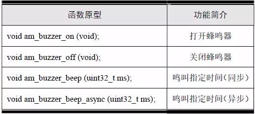
The interface has no special description, and directly defines the return value of all interfaces as the standard error number of type int. Based on this, the complete definition of the buzzer control interface is shown in Table 8.5.
Table 8.5 Buzzer Universal Interface (am_buzzer.h)
The corresponding class diagram is shown in Figure 8.8.
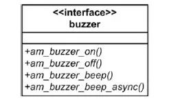
Figure 8.8 Buzzer Interface Class Diagram
> > > 8.3.2 Implementing the interface
1. Abstract buzzer equipment class
The buzzer has a total of four general-purpose interfaces. The am_buzzer_beep() and am_buzzer_beep_async() interfaces can be directly implemented based on the am_buzzer_on() and am_buzzer_off() interfaces. The implementation of am_buzzer_beep() is shown in Listing 8.24.
Listing 8.24 Implementation of am_buzzer_beep()
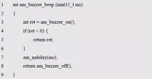
In the program, first use am_buzzer_on () to open the buzzer, if the buzzer is turned on (the return value is negative), the corresponding error number is directly returned. If the opening is successful, the specified time is delayed using am_mdelay(), and finally Turn off the buzzer. For the am_buzzer_beep_async() interface, it needs to be returned immediately. The delay function cannot be used directly inside the function. It can be implemented based on the software timer. The sample program is shown in Listing 8.25.
Sample Listing 8.25 am_buzzer_beep_async() sample program
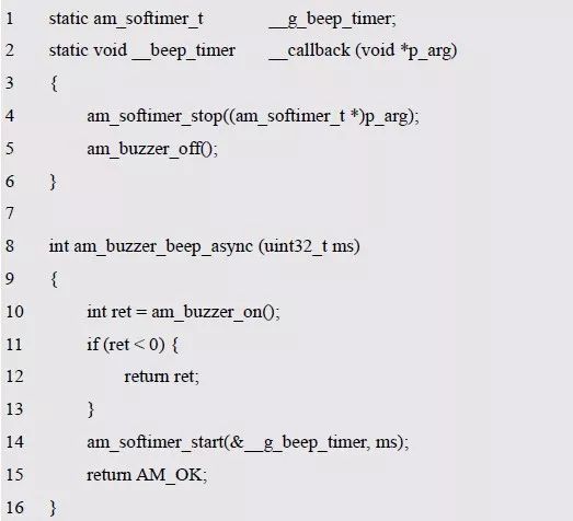
In the program, first use am_buzzer_on () to open the buzzer, if the buzzer is turned on (the return value is negative), the corresponding error number is directly returned. If the opening is successful, the software timer is started, and the timing is the specified tweet. Time, the function returns immediately after starting the timer. After the software timer expires, you need to call the custom callback function __beep_timer_callback(). In the callback function, the software timer and buzzer are turned off and the tweet ends.
Obviously, the software timer needs to be initialized before use, so that the __beep_timer_callback() function is used as the callback function after its timing time, such as:

Where is the initialization statement placed? Here is just an example of using the software timer to implement the am_buzzer_beep_async() function. The appropriate timing for initializing the software timer is described later.
Since the am_buzzer_beep() and am_buzzer_beep_async() interfaces can be directly implemented based on am_buzzer_on() and am_buzzer_off(), the core of the buzzer interface is to implement the am_buzzer_on() and am_buzzer_off() interfaces, which can be abstracted according to the LED or HC595 design method. Corresponding two methods. which is:

Although it is completely feasible according to this design method, considering that on and off are a set of mutually symmetric interfaces, the functions are of the same class and have great similarities. Therefore, it is possible to abstract only one method and use a Boolean. The parameter of the type distinguishes whether the operation is on or off, such as:

It can be seen that the definition of the abstract method is not necessarily the original abstract method according to the interface definition, and can be appropriately adjusted, as long as the general interface can be implemented based on the abstract method.
Although there is only one abstract method, in order to ensure the unity of the structure, and to facilitate subsequent extensions (such as adding abstract methods, etc.), the abstract method is often placed in a virtual function table. which is:
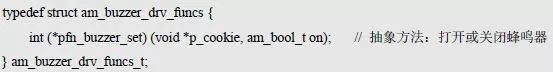
Similarly, the abstract method and p_cookie are defined together, which is an abstract buzzer device. Such as:
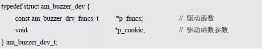
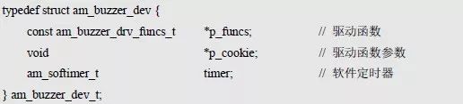
In the previous implementation of the am_buzzer_beep_async() interface, the software timer was used. Obviously, the software timer is used to implement a buzzer tweet function, which is related to the buzzer device. It should not be defined as a global variable. Instead, it is replaced by a global variable. The definition is directly in the abstract device structure, namely:
Abstract methods defined in abstract devices need to be done by specific buzzer devices, and the am_buzzer_on() and am_buzzer_off() interfaces can be implemented directly based on abstract methods.
When defining the buzzer interface, since the buzzer is a single instance device (only one in the system), there is no parameter defined in the interface to distinguish the buzzer object, such as ID number or handle parameter, then the interface is implemented. How do you find the right device? Since there is only one buzzer device in the system, you can directly use a global variable to point to the buzzer device. The implementation of am_buzzer_on() and am_buzzer_off() is detailed in Listing 8.26.
Sample Listing 8.26 Sample programs for am_buzzer_on and am_buzzer_off ()
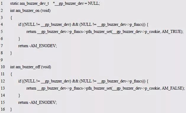
Where __gp_buzzer_dev is a pointer to the buzzer device and initially does not have any valid buzzer devices, so the initial value is NULL. Obviously, to use the buzzer properly, you must point __gp_buzzer_dev to a valid buzzer device, which requires the pfn_buzzer_set abstract method to be implemented by the specific buzzer device.
In order to complete the assignment of __gp_buzzer_dev, you need to define a device registration interface for registering a valid buzzer device with the system:

In order to facilitate the addition of a buzzer device to the system, it is avoided to directly operate each member of the buzzer device, and the member that needs to be assigned is passed to the interface function through the parameter. The implementation is detailed in Listing 8.27.
Listing 8.27 Adding a buzzer device to the system
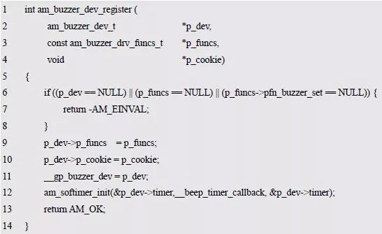
The program first determines the validity of the parameter, then completes the abstract method and p_cookie assignment in the abstract device, then assigns the global variable __gp_buzzer_dev to the valid buzzer device, and finally initializes the software timing in the abstract device. The device facilitates the asynchronous buzzer to sound the interface. It can be seen that the initialization of the software timer is completed when a buzzer device is added.
Obviously, next, you need to derive a specific buzzer device based on the abstract buzzer device, complete the abstract method pfn_buzzer_set in the specific buzzer device, and add a bee to the system using the am_buzzer_dev_register() interface. The sounder device allows the user to operate to a specific effective buzzer using the buzzer universal interface.
For ease of reference, the contents of the buzzer device interface file (am_buzzer_dev.h) are shown in Listing 8.28. The corresponding class diagram is shown in Figure 8.9.
Listing 8.28 am_buzzer_dev.h file contents
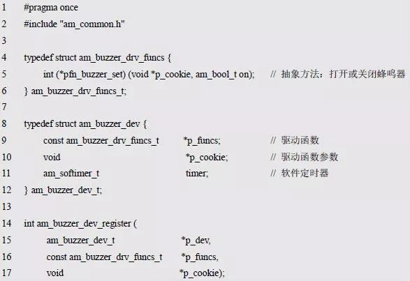
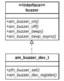
Figure 8.9 Abstract buzzer device class
2. Specific buzzer equipment class
Taking the PWM output control buzzer as an example, the implementation method of the specific buzzer device is briefly described. First, a specific device class should be derived based on the abstract device class. The class diagram is shown in Figure 8.10, which can directly define the specific buzzer device class, such as:

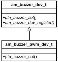
Figure 8.10 Specific buzzer device class
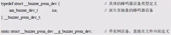
Am_buzzer_pwm_dev_t is the specific buzzer device class. With this type, you can use this type to define a specific buzzer device instance, namely:

In particular, since the buzzer is a single-instance device and cannot be defined with this type, it is possible to define a buzzer device instance directly inside a file implemented by a specific device without requiring the user to use a custom device instance of that type. . Based on this, the am_buzzer_pwm_dev_t type does not need to be open to the user and can be directly defined in the .c file. Since the am_buzzer_pwm_dev_t type does not need to be open to the user, it is only used internally, so you can modify the type name to start with the double underscore "__", as in the am_buzzer_pwm.c file. The device types defined in the device and the corresponding device instances are as follows:
When using the PWM output to control the buzzer, you need to know the handle of the PWM, the channel number and other related information. This information needs to be saved in the device, so the updated device type is defined as follows:

Obviously, these members need to be initialized before they can be used. The prototype for defining the initialization function is:

Among them, pwm_handle is the standard PWM service handle, chan is the PWM channel number, duty_ns and period_ns respectively specify the pulse width and period of the output PWM waveform, which determines the loudness and frequency of the buzzer, for example, AM824-Core onboard buzzer.
If SCT output PWM is used, since PIO0_24 corresponds to channel 1 of SCT, the initial call function is called as follows:

In the program, the am_lpc82x_sct0_pwm_inst_init() function is used to obtain the PWM handle, channel 1 is used, and the output PWM period is set to 400000ns, which is 2.5KHz (1000000000 / 400000), and the pulse width is exactly half of the period, that is, the output PWM The duty cycle is 50%. An example of the implementation of the initialization function is shown in Listing 8.29.
Listing 8.29 Initialization Function Implementation Example
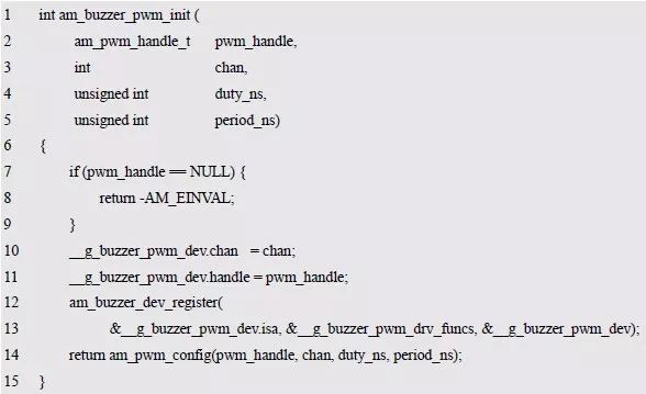
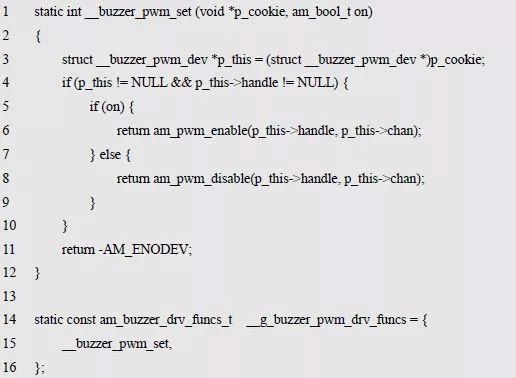
The program first determines the validity of the parameter, then completes the assignment of the relevant member in the device instance, then calls the am_buzzer_dev_register() function to add the buzzer device to the system, and finally configures the pulse width and period of the PWM output channel. . When adding a device, assign p_funcs to &__g_buzzer_pwm_drv_funcs, and p_cookie to the address of the specific device, ie p_cookie points to the device itself. The concrete implementation of the abstract method is contained in __g_buzzer_pwm_drv_funcs. See Listing 8.30 for a complete definition.
Listing 8.30 Implementation of the abstract method
For ease of reference, the contents of the buzzer device interface file (am_buzzer_pwm.h) are shown as shown in Listing 8.31.
Listing 8.31 am_buzzer_pwm.h file contents
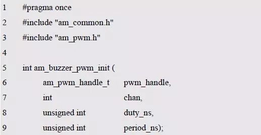
It can be seen that compared with the interface files of other specific devices (see Listing 8.14, Listing 8.17 and Listing 8.23), the difference is that it does not contain the definition of the specific device type, and initializes the first parameter of the interface. Nor is it a pointer to a specific device. This is because the buzzer is a single-instance device, and only one can be defined in the system. Therefore, the definition of the device instance is completed directly in the implementation file, and the related types need not be opened to the user. Similarly, since it is a single instance device, the initialization function initialization must be a device instance defined inside the file, and there is no need to additionally use a pointer to the device to specify the device to be initialized.
So far, the LED universal interface, HC595 interface and buzzer interface are described in detail, which represent the typical three types of device interfaces in AMetal.
LED universal interface: Different devices are distinguished by unique IDs;
HC595 interface: Use handles to distinguish between different devices, the handle is essentially a pointer to the device;
Buzzer interface: A single instance device that does not use any parameters to distinguish different devices.
8.4 Temperature Acquisition Interface
> > > 8.4.1 Defining interfaces
1. Interface naming
Since the object of operation is temperature, in order to shorten the interface name, temperature is abbreviated as temp, so the interface name is prefixed with "am_temp_". For temperature acquisition, the main operation is to read the current temperature. The definable interface name is:
Am_temp_read
2. Interface parameter
Obviously, there may be multiple temperature sensors in a system, and the handle can be used to distinguish different temperature sensors. Therefore, the type of the first parameter is defined as the temperature sensor handle. Similar to the HC595 device, it should be defined as pointing to the abstract temperature device. The pointer, assuming the type of the abstract temperature device is am_temp_dev_t, the type of the handle can be defined as:

The core function of the read temperature interface is to return the current temperature value. First, you need to define the type of the temperature value, and then determine the return method of the temperature value: return by return value or return by exit parameter.
Usually, a decimal value is used to represent the temperature value, for example, 37.5 °C. It can be seen that the temperature value needs to be represented by a decimal number, but the required precision is not high, and it is often only accurate to one decimal place. Therefore, the temperature value can be used as the float type. Said.
Since the actual hardware platform that Ametal runs is often a low-end Cortex-M0, Cortex-M0+, and Cortex-M3 core chips, these chips do not have hardware floating-point arithmetic units, and the efficiency of floating-point operations is very low. Therefore, in the AMetal platform, the floating point type is not recommended. According to this, the integer can be used to represent the temperature value. At the same time, in order to ensure a certain precision, the integer value is used to express the temperature value after the expansion by 1000 times. If the actual temperature is 37.5 degrees, it is represented by the integer 37500. Using this method cleverly avoids the use of floating point types, but also ensures that the accuracy of the actual temperature is three decimal places. Since the temperature may have a negative value, the signed 32-bit data is used to represent the temperature value, ie the type of the temperature value is defined as int32_t.
In the generic interface, the return value is often defined as an error number of type int, and a negative number is used to indicate an error. Obviously, if the return value is used to directly return the temperature, the user will not be able to distinguish between a negative temperature and a read temperature error. To do this, use an output parameter to return the temperature value, ie define a pointer of type int32_t as the output parameter:
Am_temp_read(am_temp_handle_t handle, int32_t *p_temp)
Where handle is the handle of the temperature sensor and p_temp is the output parameter, which is used to return the current temperature value, which represents the temperature value 1000 times of the actual temperature value.
3. return value
The interface has no special description, and directly defines the return value of all interfaces as the standard error number of type int. Based on this, the prototype of the complete read temperature interface is:

The corresponding class diagram is shown in Figure 8.11.
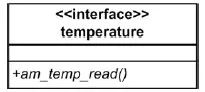
Figure 8.11 Temperature Acquisition Interface
> > > 8.4.2 Implementing the interface
1. Abstract temperature acquisition device class
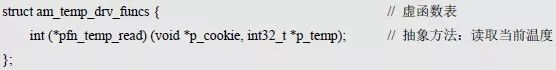
According to the read temperature interface, you can define the corresponding abstract method and store it in a virtual function table:
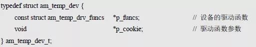
Similarly, the abstract method and p_cookie are defined together, which is an abstract temperature acquisition device. such as:
Obviously, the specific temperature acquisition device is directly derived from the abstract temperature acquisition device, and then the specific temperature acquisition device realizes the abstract method of reading temperature according to the actual hardware.
In the read temperature interface, the handle is used as the first parameter, which is essentially a pointer to the device. The read temperature interface can directly call the abstract method implementation. See Listing 8.32 for details.
Listing 8.32 Reading Temperature Interface Implementation
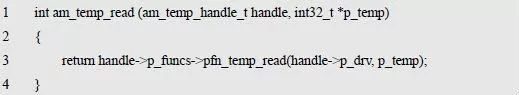
In the interface implementation, there is no hardware-related implementation code, just a simple call to the abstract method. The abstract method needs to be implemented by a specific temperature acquisition device. Similarly, since the implementation of the read temperature interface is very simple, its implementation is often stored directly in the .h file as an inline function.
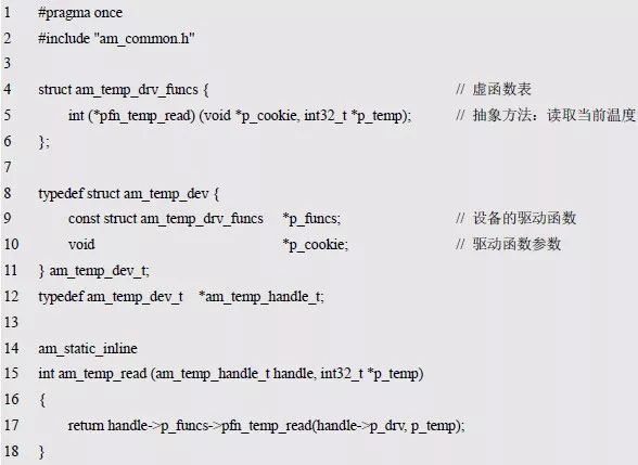
For ease of reference, the contents of the abstract temperature acquisition device interface file (am_temp.h) are shown in Listing 8.33, which contains the abstract method definitions, type definitions, and interface implementations associated with the abstract temperature acquisition device. See Figure 8.12.
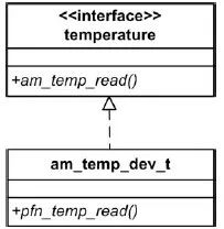
Figure 8.12 Abstract temperature collection device class
Listing 8.33 am_temp.h file contents
2. Specific temperature collection equipment
Taking the LM75B temperature sensor for temperature acquisition as an example, the implementation method of the specific temperature acquisition device is briefly described. First, a specific device class should be derived based on the abstract device class. The class diagram is shown in Figure 8.13, which can directly define the specific temperature collection device class. such as:
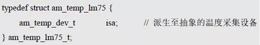
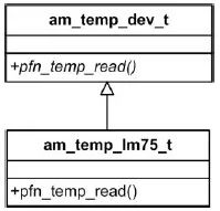
Figure 8.13 Specific temperature collection equipment class
Am_temp_lm75_t is a specific temperature collection device class. After this type, you can use this type to define a specific temperature acquisition device instance:

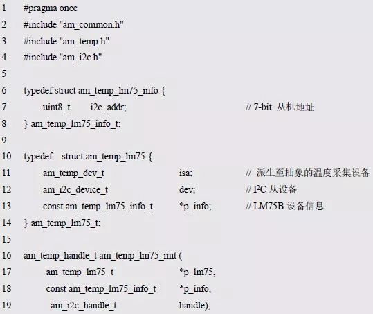
The LM75B is a standard I2C slave device that requires the slave address of the LM75B to be used to read the temperature data in the LM75B using the I2C bus. Since the slave address is related to the LM75 external pin level, the address information of the LM75 needs to be set by the user according to the actual hardware circuit. Store device-related information that needs to be provided by the user into a new device information structure type. such as:
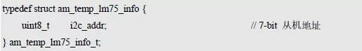
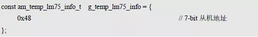
When using the LM75B onboard the AM824-Core, the 7-bit I2C slave address of the LM75B is 1001A2A1A0. Since A0, A1, and A2 are both tied low to ground, the 7-bit slave address of the onboard LM75B is available. It is 1001000, ie: 0x48. Based on this, the device instance information corresponding to the onboard LM75B can be defined as follows:
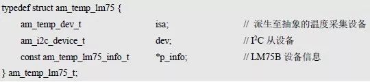
For the same reason, it is necessary to maintain a pointer to device information in the device class. In addition, since the temperature data is read from the LM75B using the I2C interface, the LM75B is equivalent to an I2C slave. To communicate with the I2C interface, you need to define a corresponding I2C slave for the LM75B. Two new members are added. The complete temperature acquisition device definition is:
Obviously, before using the I2C interface to read the temperature from the LM75B, you need to complete the assignment of each member of the device. This is usually done in the driver's initialization function. The prototype that defines the initialization function is:
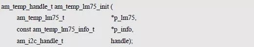
P_lm75 is a pointer to an instance of type am_temp_lm75_t;
P_devinfo is a pointer to the instance information of the am_temp_lm75_info_t type.
Handle is an I2C handle, which is convenient for reading temperature data using the I2C interface. The return value of the initialization function is the handle of the temperature acquisition device. The call form is as follows:

The return value is the handle of the temperature acquisition device, which can be used as the actual parameter of the first parameter of the temperature acquisition interface. The implementation example of the initialization function is shown in Listing 8.34.
Listing 8.34 Initialization Function Implementation Example
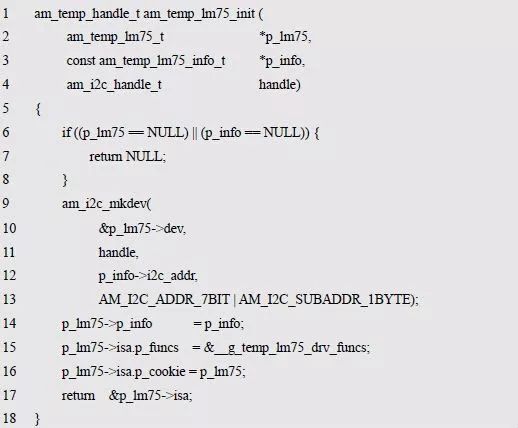
The program first establishes a standard I2C slave device, which facilitates subsequent reading of data using the I2C interface, then initializes the p_info member, then completes the assignment of p_funcs and p_cookie in the abstract temperature acquisition device, and finally returns the device address as the user operating temperature acquisition device. Handle. Pfuncs is assigned the value of &__g_temp_lm75_drv_funcs, which contains a concrete implementation of the read temperature abstraction method. See Listing 8.35 for a complete definition.
Listing 8.35 Implementation of the abstract method
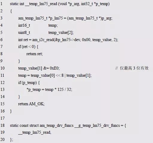
In the read temperature implementation function __temp_lm75_read(), the current actual temperature value is first read from the LM75B using the I2C interface, as shown in Listing 8.35(6); then the data is simply processed, and the two-byte data is integrated. For a 16-bit signed temperature value temp, see Listing 8.35 (10 ~ 11); finally, after confirming that the p_temp pointer is valid, multiply temp by 125 and divide by 32, and the final result is used as the output temperature value.
Why multiply temp by 125 and then divide by 32? This is because the data directly read in the LM75B is 256 times the actual temperature value, ie: actual temperature = temp / 256.
The temperature collection interface needs to return a temperature value that is 1000 times the actual temperature, namely:
* p _ temp = actual temperature * 1000 = temp / 256 * 1000 = temp * 1000 / 256
Simplification is available:

For ease of reference, the contents of the specific temperature acquisition device (LM75B) interface file (am_temp_lm75.h) are shown in Listing 8.36.
Listing 8.36 am_temp_lm75.h file contents
Wire harness and the surrounding parts shall be even and sufficient distance shall be kept from the heat source,
Considering the protection against electromagnetic interferencee,
Consider assembly technology, maintenance technology,
Grounding wire layout,
Heat dissipation of wire harness and fuse box
Car Seat Harness,Power Seat Wiring Harness,Power Seat Harness,Right Seat Wire Harness
Dongguan YAC Electric Co,. LTD. , https://www.yacentercn.com