Whether it is a grain warehouse, a Chinese medicine warehouse, or a book. All need to be in compliance with the specified temperature and environmental conditions. Temperature is the most difficult indicator. In response to this situation. It is extremely important to develop a reliable, convenient and timely temperature control system. Use D1S18B20 to collect digital signals, through Bluetooth wireless communication technology and USB interface technology. A monitoring system that detects and controls the temperature by the 89S52 single-chip microcomputer is realized. The whole system consists of acquisition board, communication board and PC monitoring program. The acquisition board uses the temperature monitoring chip DS18B20t21, the single chip chip AT89S52 and the bluetooth chip BC4 as the core time-sharing to complete the command of the monitoring host and data acquisition and data transmission. The working state of the system can be changed at any time according to the command of the received host. The communication board takes the USB chip PDIUSBD12 and the single chip microcomputer AT89S52 as the core, realizes data receiving, data transmission, and displays the collected external signals in real time on the PC interface through the waveform diagram. Also save the data to the database.
Bluetooth module - wireless receiving and transmitting circuit
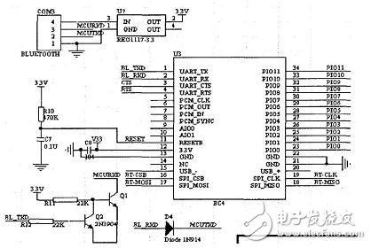
The system uses the CSR Bluetooth chip BC417143. The chip uses Blue4.0, supports master or slave mode, supports AT command set, supports baud rate of 2 400 to 1 382 400 bps, and is suitable for embedded serial port transmission wireless new module. It is worth noting. The Bluetooth chip operates at 3.3 V and the MCU operates at 5 V. There is a logic level mismatch. And the IO pin cannot tolerate the 5 V logic level of the MCU. The design uses 1117 chip for level conversion output 3.3 V. Bluetooth and MCU connection need to be level-limited to ensure the normal operation of the Bluetooth module, the following is the power selection scheme of the Bluetooth module and the pin definition of the serial port module.

Figure 3 Circuit diagram of the Bluetooth module
Acquisition board circuit schematic
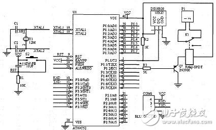
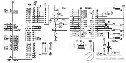
The circuit diagram of the acquisition board is shown in Figure 4. The Bluetooth module is mainly connected to the serial IO port of the microcontroller. The digital temperature sensor DS18B20 is connected to the P1.0 port of the microcontroller. The relay is connected to the P1.2 port. The temperature sensor DS18B20 converts the temperature into a digital signal and sends it to the microcontroller via P1.0 El. The data processed by the single-chip microcomputer is transmitted from the serial port to the Bluetooth module (BLUETOOTH). The Bluetooth module can also receive the command sent by the communication board. 2-2 Communication board circuit design The communication board is mainly composed of a single-chip microcomputer, a Bluetooth module, a USB module and the like. As shown in the figure, PDIUSBD12 is a cost-effective USB device. It is commonly used as a high-speed general-purpose parallel interface for implementing communication with a microcontroller in a microcontroller system. It also supports DMA transfers and it also integrates many features. All of these features, including SoftConnetTM, GoodLinkTM, programmable clock output low-frequency crystals, and termination register sets, provide significant system cost savings. At the same time, the application of the USB function on the peripheral is made easy.

Figure 4 Schematic diagram of the acquisition board circuit
The 8 DATA pins of PDIUSBD12 are connected to the PO port of the microcontroller, and the 10 kΩ resistor is used as the pull-up resistor. SUSPEND is the output when the chip is suspended. Connect to the P1.1 of the microcontroller: INT_N is the interrupt request. Connect with the IN, m of the MCU: RD N and WR N read and write strobe signals are respectively connected to the RD and WR of the MCU; DMREQ, DMACK N, EOT N are the DMA interrupt request, DMA response and DMA transfer respectively. Since the DMA function is not used, it is directly connected to the high level. RESET N is the reset pin. Connect to the single-chip P1.7; GL N is the working indicator of the chip. Receive an LED indicator. You can directly observe the operating status of the USB device; XTAL1 and XTAL2 are connected to 6MHZ.CS N as the chip select signal. Connect to the PI.6, A0 address line of the single-chip microcomputer, use the I/O port to simulate, connect the single-chip microcomputer P3.4: D+ and D one is the differential data line of USB and connect an impedance matching resistor of l8 Q respectively. Connected to the USB plug.
The Bluetooth module connection method is the same as that of the acquisition board.
The signal flow of the communication board is: the temperature data collected by the acquisition board is transmitted to the communication board via the Bluetooth module, and sent to the MCU for processing. Transfer to the PC via PDIUSBD12 for display saving. When a single user operates on a PC, data is transferred from the PC to the microcontroller via PDIUSBD12. After Bluetooth transmission, it is sent to the acquisition board for relative response.

Figure 5 Communication board circuit schematic
Electronic enthusiast network technology editors comment analysis:
This paper presents a design scheme of a wireless temperature monitoring system based on USB and Bluetooth chip BC417143. And introduced the design process of the system from the hardware aspect. Wireless data acquisition for temperature information is achieved. The Bluetooth chip is used as a wireless transceiver module. The DS18B20 is used as temperature data acquisition. The USB interface chip acts as a communication interface with the PC. It simplifies circuit design and is easy to expand and network.
If you have any questions, please feel free to discuss them in the comments section.
- Electronic enthusiast network finishing, please indicate the source!
Fork Type Terminals,Insulated Bullet Sockets Terminals,Insulated Bullet Terminals,Type Fork Insulate Terminal
Taixing Longyi Terminals Co.,Ltd. , https://www.longyicopperterminals.com