1 Introduction
At present, in the automotive field, the method of remote key entry, keyless entry, and startup is basically realized. UHF receiving modules are used for both RKE (Remote Keyless Entry) and PKE (Passive Keyless Entry) systems. The design of the UHF module plays a very important role in the overall system performance.
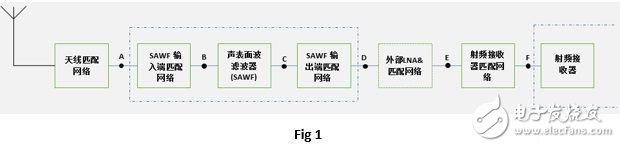
The UHF receiving module is generally composed of the following parts: antenna, surface acoustic wave filter (SAWF, optional), external low noise amplifier (Ext. LNA, optional), UHF receiver chip (UHF Receiver), and these components An impedance matching circuit between. As Fig 1.
For the entire receiving module, in the case of good PCB design, the optimization of hardware performance mainly focuses on how to perform impedance matching between each sub-module, so that the loss of signal between each module is minimized. This article focuses on the method of impedance matching for UHF receiver modules.
In general, there are two ways to match impedance: one is direct matching and the other is indirect matching.
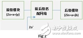
The so-called direct matching means that the output impedance of the pre-stage module of the system and the input impedance of the sub-module are matched directly through only one matching network. As shown in Fig. 2. Since the purpose of the match is to get the optimal power transfer, this match can be called power matching or conjugate matching. For example, suppose the output impedance of the pre-stage module is Zo=x+jy ohm, and the input impedance of the post-stage module is Zin=a+jb ohm. After matching the network, the impedance from the output of the pre-stage module to the subsequent stage is Zo′= Zo*, ie Zo'=x-jy. This way the conjugate matching can be said to be completed.
Indirect matching, as shown in Fig. 3. Match the front stage output impedance and the post stage input impedance to 50 ohms. In this way, the front and rear stages are matched by the "middleman" of 50 ohms. This is called indirect matching.

For the system, there are many factors to consider when deciding whether to choose direct or indirect matching. In general, the advantage of direct matching is mainly that fewer matching components are required, the loss is naturally smaller, the PCB space is small, and the PCB design is easy; the disadvantage is that sometimes the output impedance of the previous stage is more difficult to measure, and only through query related According to the specification, the result may be relatively large; because the modules are matched by any impedance, and the general RF test equipment is 50ohm input/output impedance, it is inconvenient to test the performance between each module node. In contrast, indirect matching requires more matching components and takes up more PCB space; but the advantages are equally prominent. Since the modules are matched to 50 ohms, the performance of each module node is relatively easy to test.
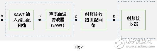
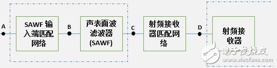
This article will use the following (Fig 4) module architecture as an example to show how to perform step-by-step matching. It can be seen that both indirect and direct matches are included.
2 Impedance matching steps
Equipment commonly used for impedance matching in the laboratory is: network analyzer (for impedance testing and matching), RF signal generator (for testing and validation of matched performance), SmithChart simulation software, and sometimes A digital model generator is used. In the car access control system, the commonly used frequency bands are 315MHz, 434MHz, 868MHz, 915MHz. Let us use the 434MHz frequency band as an example to illustrate the whole process.
This article uses the following (Fig 4) module architecture as an example to introduce how to perform impedance matching.
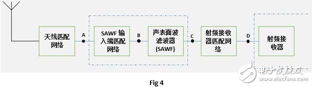
The process of impedance matching is generally: matching of the antenna module, matching of the RF receiver and the SAWF output, and matching of the SAWF input.
2.1 Antenna matching
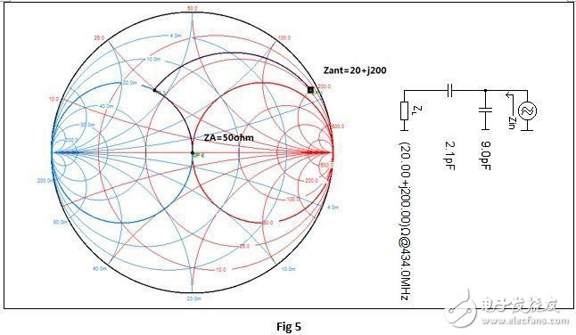
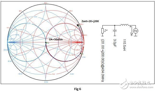
Due to the different types of antennas used, the impedance of the antenna will vary greatly, either as inductive, capacitive or pure. Suppose the measured antenna impedance is Zant=20+j200. Let's see how to match.
There are many topologies for impedance conversion from Zant to 50 ohm, which can be achieved with a minimum component principle. The distribution of L&C, C&L, C&C, L&L of the specific L-type network can be selected according to the specific high-pass filter type, low-pass filter type, band-pass filter or DC-blocking type.
It can be seen from the SmithChart simulator simulation (Fig 5) that the antenna can achieve ZA=50 ohm impedance at point A of Fig 4 by connecting 2.1pF in series with a 9pF capacitor in parallel. This matching is the most economical method, as long as two capacitors can be implemented.
However, if both impedance matching and low-pass filtering are required, it can be implemented in the form of Fig.
By analogy, a matching network with high-pass filtering can also be obtained.
Antenna matching can be done in this way. Looking at the antenna at point A, a 50 ohm impedance is obtained by matching the impedance conversion of the network.
After the above matching, the performance of the antenna can be tested directly in a special anechoic chamber. The gain, directionality, field distribution and other properties of the antenna are important parameters, and the impact on the overall system performance is also relatively large.
It should be noted that since the module has an outer casing and is then placed in the car, the performance of the antenna is greatly affected by the outer casing and the interior environment. When performing antenna impedance matching, be sure to pay attention to the actual working environment. It is best to install the module into the casing and place it in a fixed position in the car for impedance matching. If this is really difficult, you can also use the car rig to operate.
2.2 Matching of RF Receiver and SAWF
As can be seen in Fig 4, only one matching network is used between the SAWF output and the RF receiver, which is the direct matching mentioned above. In systems that are determined to use SAWF, it is generally sufficient to confirm the sensitivity of the SAWF plus the RF receiver, as the insertion loss of the SAWF is generally known. Of course, if you really need to test the sensitivity of the RF receiver separately, you can add a matching network here to match the SAWF and the RF receiver to 50 ohms, respectively, provided there is enough space between them to arrange the components.
Let's discuss the impedance matching method based on Fig 7.
Step 1: Confirm the input impedance of the RF receiver.
The input impedance value of the RF input or the equivalent R//C value is indicated in the data sheet of the RF receiver. Some readers will use this value directly to match the value of the chip's RF input. It should be noted here that this value is generally the ideal value of the chip design, and there are generally large differences in the specific PCB boards.
The correct way is to power on the receiver, and the chip is in the receiving state through the host computer or the internal program of the chip. If there is a low noise amplifier inside, it should be in the maximum gain state, and adjust the output power of the network analyzer to make the chip. The internal amplifier circuit operates in a linear amplification state to prevent it from saturating, thereby affecting the result. The general power setting below -60dBm can meet the requirements, please refer to the chip data sheet for details.
Here we assume that the input impedance of point D is measured as Zrx_in=200
Step 2: View the SAWF data sheet to find the output impedance value.
Since the output impedance of the SAWF is difficult to measure in the laboratory, we temporarily assume that its value is shown in the data sheet. such as
Zout=60-j150.
Step 3: Conjugate matching the chip input and the SAWF output.
Narrowband SAWFs are generally designed for power matching, ie conjugate matching.
This step mainly uses the Smithchart simulation tool, which does not require a network analyzer for the time being. Since the output impedance of the SAWF is difficult to measure, we simulate the required matching network based on the assumptions. In the next steps, we will verify this hypothesis.
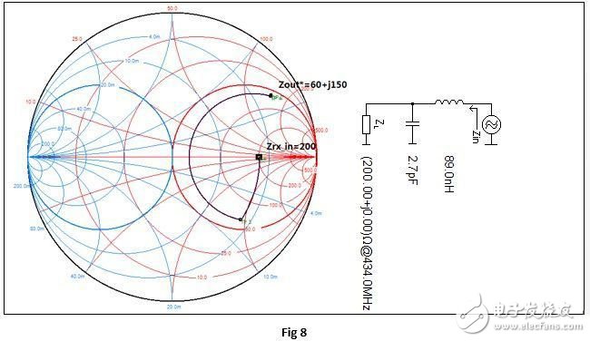
As seen in Fig. 8, the input impedance of the RF receiver is obtained by connecting a 2.7pF capacitor and a 89nH inductor in series to obtain an impedance Zout*=60+j150 ohm at point C, which is the conjugate impedance of the SAWF output impedance Zout.
Here, the matching between the RF receiver input and the SAWF output is basically completed. The next steps will in turn verify the results of this step.
Step 4: Match the SAWF input
The matching of this step is closely related to step 3. First, the settings of the receiver and the network are the same as in step 1.
At point A, the input impedance is measured with a mesh, and the input matching network is adjusted so that the measured impedance at point A is 50 ohms. The specific method is described in detail in "Reference 1".
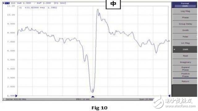
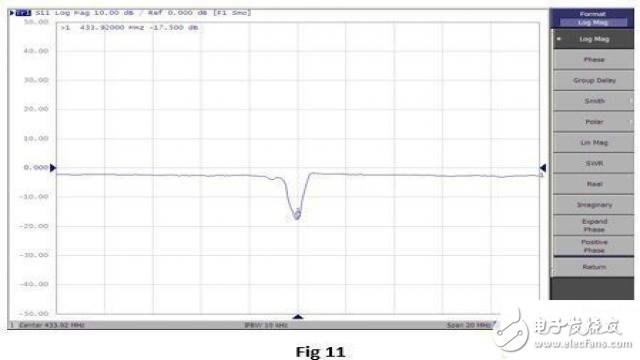
Assume that the impedance measured at point A is similar to that shown in Fig. 9. It can be seen that the impedance at this time is ZA=43-j9 ohm. We changed the network analyzer measurement format to the standing wave ratio and Log Mag to confirm the matching performance, as shown in Fig. 10, Fig 11. You can see VSWR=1.39, Log Mag=-17.5dB. Log Mag "-10dB is generally required, so the current match is very good.
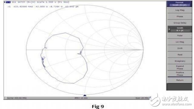
In Fig. 9, we noticed that there is a coiled ring near 434MHz, which is due to SAWF. It can be seen that the ring here is very small and very close to 50 ohms, indicating that the matching of steps 3 and 4 is successful.
If the result shows that the loop of the curl is relatively large, it indicates that the match in step 3 has a deviation, and it is necessary to adjust the value of the matching network component until the desired result is achieved.
Step 5: Test and verify the performance from SAWF to the chip
At this point, the entire matching work is basically completed, and the matching results need to be tested and verified.
Generally, the RF signal generator is used to input the modulation signal from point A, and the sensitivity of the chip is tested by reducing the power of the input signal. According to the setting description and evaluation criteria on the chip manufacturer's specification, the result is compared with the sensitivity of the corresponding chip specification. If the results are close, the matching is good. If the result is different, the matching is needed. The result is fine-tuned.
If the matching is performed according to the above steps, no obvious errors will occur during the period, and the final result will be very close to the result of the chip manufacturer.
Step 6: Verify the performance of the entire module
Finally, connect the antenna to all subsequent submodules and measure the performance of the module according to different customer requirements.
| About Enameled Copper Wire |
Henan HuaYang Copper Group Co.,Ltd specialized in producing enameled copper wire for 25 years ,Products including PEW enameled copper wire, EIW Enameled Copper Wire, EI/AIW enameled copper wire, EIW/A Enameled Copper Wire,and Enameled and glass-fiber copper wire.
According to the characteristics of motor, transformer, automotive electrical and high-speed winding machine, we have advantages in resilience, breakdown voltages and have imported machine to protect the quality of Enameled copper wire.
After 25 years of efforts, we have good reputation from foreign and domestic.

Product Feature.
Enameled
Copper Wire
Conductor
Copper
Dimension
Diameter(mm):
0.15 ~ 3.0
Thermal
Class(℃)
130(Class
B); 155(Class F); 180(Class H); 200(Class C); 220(Class C+);
Standard
IEC;
Packing
PT4
– PT200 or ply-wood spool
Application
Transformer;
motor; generator; modern instrument; welding machine and so on
About
Factory.
For quality of Enameled Copper Wire, we have imported machine and R&D. we checked every spools of products after finishing the products.


'Quality and efficiency' is our principle.
Enameled Copper Wire,Enameled Magnetic Copper Wire,Rewding Enameled Copper Wire,Winding Enameled Copper Wire
HENAN HUAYANG ELECTRICAL TECHNOLOGY GROUP CO.,LTD , https://www.huaonwire.com