The basic rules for the implementation of the function table diagram conversion and the precautions for drawing the function table diagram;
The complex control system not only has a large number of I/O points, but also a complicated function table. In addition to the basic structure of the function chart shown above, it also includes skipping and loop control, and the system often requires multiple working modes. Such as manual and automatic (including continuous, single cycle, single step, etc.) work mode. The manual program is relatively simple, generally designed by empirical method, and the design of the automatic program generally uses the sequential control design method.
1. Jump
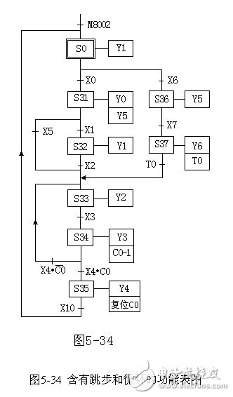
The state machine is used to represent each step as shown in Fig. 5-34. When step S31 is the active step, and X5 becomes "1", step S32 is skipped, and step S31 is advanced to step S33. This kind of jump is the same as the direction of the directed line in the "main sequence" composed of S31 S32 S33, etc., called forward jump. When step S34 is the active step and the condition is switched, the process returns from step S34 to step S33, which is opposite to the direction of the directional connection in the "main sequence" and is referred to as a reverse skip. Obviously, a jump is a special case of a selection sequence.
2. cycle
When designing a ladder program, you often encounter operations that require multiple iterations. If you program it once and for all, it is obviously very cumbersome. We often use a cyclical approach to design the function chart and ladder diagram, as shown in Figure 5-34. Assume that the process consisting of step S33 and step S34 is repeated 10 times, and the number of cycles is controlled by C0. The value is equal to the number of loops 10. Each time the loop is executed, the current value of C0 is decremented by one in step S34. This operation is performed by connecting the normally open contact of S34 to the count pulse input terminal of C0. When step S34 becomes the active step, S34 The normally open contact changes from off to on, decrementing the current value of C0 by one. Each time the last step of the execution cycle is performed, it is determined whether the loop should be ended according to whether the current value of C0 is zero. The figure is implemented by selecting the branch of the sequence after step S34. Assuming X4 is "1", if the loop is not over, the normally closed contact of C0 is closed, the transition condition is satisfied and returns to step S33; when the current value of C0 is reduced to 0, its normally open contact is closed, and the transition condition is satisfied, Step S34 proceeds to step S35.
The counter of the control loop should be reset before or after the execution of the cyclic program to ensure the loop count for the next cycle. The reset operation should be placed outside the loop. It is obviously convenient to reset the counter in steps S0 and S25 in Figure 5-34.
24V Charger,24V Ebike Charger,Electric Charger For Motor,24V Battery Charger
HuiZhou Superpower Technology Co.,Ltd. , https://www.spchargers.com