The LED multi-function display system adopts the dynamic scanning method. The STC89C58RD+ single-chip microcomputer is used as the main control chip, and the self-made infrared remote controller is used to wirelessly download information to the host display. The display screen consists of 16 & TImes; 64 dot matrix composed of 1024 bright red-emitting diodes. The line scan circuit is driven by 74HC154 decoder chip, the column scan circuit is driven by 8 74HC595, and the infrared remote control transmitter adopts integrated infrared transceiver. The system implements numbers. letter. Dynamic and static display of Chinese characters and other information, and serial communication with the PC to update the display information, the system can also remotely move the information up and down and left and display the content through the remote control keyboard.
With computers and related microelectronics. With the rapid development of optoelectronic technology, LED displays are highly reliable. long lasting. Strong environmental adaptability. The cost-effective feature has rapidly grown into a mainstream product for flat panel displays.
At present, most LED dot matrix display systems have their own fonts, and the implementation of display and dynamic effects (mainly scrolling of display content) relies on hardware scan driving. Although this method is convenient, the display content is not easy to update in time, and when the LED display is When installed outdoors, it cannot be effectively controlled. The indoor display is controlled by the data line, which is very inconvenient.
The design is carried out around the multi-function LED display screen, and the display mode is up, down, left and right, and the real-time control and update of the display content is performed by using the PC. The system uses infrared emission. The remote control circuit formed by the receiver, the remote control receiver completes the entire infrared remote control transmission by receiving and recognizing the infrared light and judging the control operation. The receiving process can conveniently update the display content and replace the display mode, so that the design is more practical and convenient for operation control.
1 overall design
LED display screens use dynamic scanning display mode. The principle of scanning display is based on the persistence phenomenon of the human eye. Each display line (column) is displayed in turn. As long as the refresh frequency is not less than 24 f/s, the human eye will feel a complete continuous image.
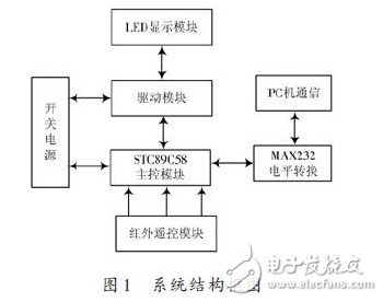
The infrared remote control transmits the control information by using infrared rays as a carrier, and the infrared emitting head adopts an infrared light emitting diode, so that the remote control transmitter is easy to be miniaturized and inexpensive. The digital signal coding and the secondary modulation method can not only realize the control of multi-channel information, increase the remote control function, improve the anti-interference of signal transmission, reduce malfunction, and low power consumption, no signal crosstalk, and fast response speed. High transmission efficiency, stable and reliable operation. The single-chip microcomputer adopts STC89C58RD+, the stored data amount is larger than STC89C52, and the crystal oscillator uses 22.1148 MHz to increase the refresh frequency to make the display more stable. After the P0 port output line signal is decoded by 74HC154, the line strobe signal is sent to the display line for rotation. display. The P2 port of the MCU is connected to the 8-bit shift register 74HC595. The overall structure of the system is shown in Figure 1.
2 hardware circuit design
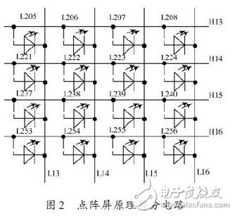
2.1 16&TImes;64 LED dot matrix screen
The system display was built with 16 rows and 64 columns of bright white 5 mm LED red diodes. The anodes of each of the 64 LEDs are connected to each other and lead out. 16 rows and 16 interfaces are used as the common anode line interface end, which is convenient to be connected with the row driving module to realize the positioning and scanning of the rows; the cathodes of each column of 16 LEDs are connected and led out. Each 8 column lines form an interface, which is convenient for connection with the column driver module, realizes storage and scanning of register data, and thus builds a display system. Part of the dot matrix circuit is shown in Figure 2.
2.2 main control and scan drive circuit
The main control circuit takes the STC89C58RD+ chip as the core and external reset circuit. The clock circuit and the serial port download line interface circuit (RS 232 communication interface) are used for communication between the LED display system and the computer. The communication mode is 10-bit asynchronous communication, and the online download is convenient for program update, which is beneficial to system maintenance.
The scan drive circuit consists of row and column drivers. The LED display has a total of 16 lines. A 74HC154 is used to decode 16 rows of LEDs. After TIP127 is amplified and converted to a high level, the line is strobed.
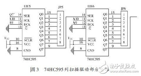
The column scan driver adopts the parallel data serial transmission scheme. The data latch is driven by the 74HC595.64 column with 8 74HC595 chips. The 8 74HC595s are connected end to end. The shift output of the previous 74HC595 is connected to the next 74HC595 input. The serial data input of a 74HC595 is connected to the data output of the MCU. The first two 74HC595 connections are shown in Figure 3.
2.3 infrared transceiver remote control circuit
The principle of infrared emission receiving is: the input signal of the transmitting end is amplified and sent to the infrared transmitting tube for transmission. At the receiving end, after receiving the infrared signal, the receiving tube is amplified by the amplifier to be reduced into a control signal. When a certain button is pressed, the MCU recognizes the button, and the MCU transmits a pulse of a certain frequency to the port connected to the infrared transmitting tube. The pulse is modulated with a carrier pulse of about 38 kHz, and then the modulated pulse is buffer amplified, and the infrared light emitting diode is excited to convert the electrical energy into light energy, so that the infrared light emitting diode emits a certain frequency of infrared light. After receiving the infrared light, the receiving control system obtains the frequency of the infrared light by the timer/counter in the single chip, and then sends the frequency to the CPU, and the CPU decodes the signal to identify the control signal, thereby implementing the control circuit. Control function to complete the entire remote control function.
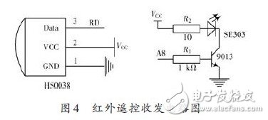
The system adopts the integrated infrared receiving head HS0038. As shown in Figure 4, the 1-pin GND is connected to the power ground, the 2-pin VCC is connected to +5 V, and the 3-pin OUT is the data output (TTL level, inverting output), which can be directly The microcontroller is connected.
SE303 is an infrared emitting diode. When P2.0=1, transistor 9013 is turned on, and SE303 is energized to emit infrared rays. Actually, it emits a pulse train with a frequency of 38 kHz. The circuit connection is shown in Figure 4.
Intel I5 Laptop is the one of the important high cpu processors, another ones are i3, i7, i9. We can do 2th, 4th, 5th, 6th, 8th, 10th, 11th or 12th. How to choose a best suitable one? If you do heavier jobs, like interior design, music or video editing, even engineering drawing, etc, 15.6 inch Intel I5 11th Generation Laptop or Intel I5 10th Generation Laptop is a better choice for you. If you focus on portability, Laptop 14 Inch I5 11th generation is a good option. Of course, Intel i7 11th Generation Laptop or 1650 graphics card laptop also available.
Someone may worry the custom one quality, that`s cause that lack of custom Student Laptop knowledge, so just keep reading so that know deep in this field. Frankly speaking, the technical skill is totally mature, no matter hardware or software or craft. You can see nearly no difference when check the oem laptop and brand one in person. To support clients and be confident with our product, provide sample for every clients.
Any other special requirements, you can just contact us freely or email us and share the exact details about what you need, thus right and valuable information sended in 1 working day.
Intel I5 Laptop,Intel I5 11th Generation Laptop,Intel I5 10th Generation Laptop,Gtx 1650 i5 10th Gen,Intel I5 Laptop Price
Henan Shuyi Electronics Co., Ltd. , https://www.shuyioemminipc.com