A remote-controlled floor-standing fan smokes due to water ingress, and the entire circuit board burns down, but the attached equipment is intact. The fan originally has a negative ion function module, a remote control + manual three-speed speed regulation, a time switch machine, and the negative ion module has an overload and short circuit protection function, so the idea of ​​using a common inexpensive original assembly circuit to achieve the above functions is sprouted.
First, the main control circuit
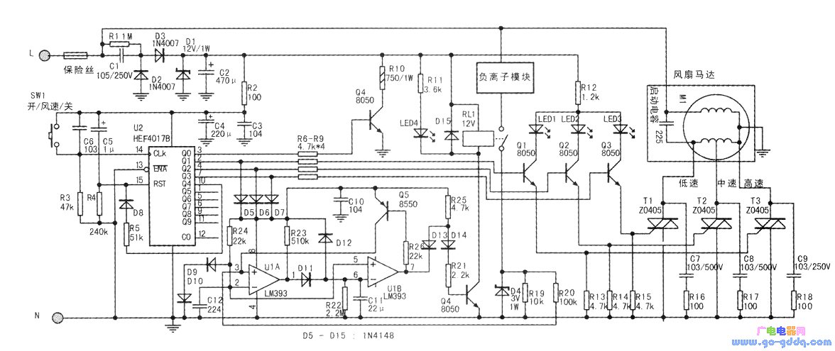
The main control circuit is shown in the figure below. It is powered by a common capacitor step-down circuit. It provides about 12V low-voltage DC from Cl, C2 and Dl~D3 for the whole circuit. Because the thyristor adopts level triggering when the whole machine is working, the trigger current needs to be large, and the value of the capacitor C1 is slightly larger. The lμF can provide more than 50 mA of working current at 220 AC input. On the other hand, in order to make the operating current of the whole machine not close to each other during startup and standby, the range of the power dissipation on D1 is too large, and the current bleeder circuit composed of Q4 and R10 is set in the standby state of the whole machine. When R10 is turned on during standby, it consumes part of the power, so that the load of D1 is too small to cause Dl to be damaged due to the load being too small in the standby state. Be careful not to reverse the power supply during installation.
Switching and gear adjustment are done by U2 and its associated circuits. At the time of power-on, the entire circuit returns to the initial state due to the reset action of C5/R4, that is, the QO pin output is high, and the other outputs are low. At this time, it is in the standby state. Only R6 and Q4 turn on the Rl0 bleed part of the current, the Ql~Q3 pins are turned off, and the fan and negative ion modules are all off. Press SW1 switch, U2 jumps to Q1 pin output high level, QO pin output jumps low.
On the one hand, the Ql pin drives the transistor Q1 to turn on, and turns on the thyristor T3, so that the fan motor runs at a high speed and simultaneously illuminates the LED 1 indicating the gear position; on the other hand, it also supplies power to the U1 and Q6 circuits through the D5.
The output load capacity of the CD4017 can exceed 3mA at 12V supply, which is sufficient to power Ul (about 1.5mA) in addition to driving the Q1 transistor to about 1.5mA. Among them, in the case that the protection function of Ul is not working, about 0.4 mA is consumed in the loop of R24-D9-Dl0, which is used to provide a relatively stable reference comparison voltage for U1; and another current of about 1 mA drives the Q6 transistor. Therefore, the relay RL1 is driven to turn on the negative ion module to continuously ionize the air during the operation of the fan, and the negative ions are continuously supplied and blown out with the wind. D8 and R5 form a function reset circuit, which returns to the initial state when SW1 is pressed for the fourth time. That is, each time SW1 is pressed to change one state, the whole machine continuously circulates in the state of “standby→high speed→medium speed→low speed→standbyâ€. .
Second, negative ions and protection circuit
The comparator reference voltage circuit is composed of R24 and D9 and D10, and the current of this circuit is about 0.3-0.5 mA. According to the specification of diode 1N4148, the forward voltage drop of this diode is about 0.55V under the forward current of about 0.4mA, and the consistency is quite good. The forward current has no obvious change when the current varies from 0.3 to 0.5mA. Therefore, the two diodes of D9/Dl0 can provide a reference comparison voltage of about 1.1V, and the negative input of the comparator UIA and the positive input of the UIB are used as the comparator reference voltage, and the voltage precision provided by the general Zener tube is Stability is still slightly higher.
In addition, a complete and independent AC loop is formed by ACL→negative ion module→relay contact→D4, R19→ACN. Under normal circumstances, Ul does not operate, and D4, D6, D7→R25→D14→R21→Q4 loop makes Q4 lead. Pass, RL1 is connected, and the negative ion module is energized. In the negative half cycle of AC, the current flow direction is ACN→D4→RL1 contact→negative ion module→ACL. Because D4 short-circuits to R19, a reverse voltage of up to 0.7V is formed on R19. This voltage will not cause U1 to operate. In the positive half cycle of AC, the current flows through R19 to generate a forward voltage drop, and the highest voltage drop corresponds to the positive peak of the AC voltage (about 311V). The detection voltage obtained on R19 is the highest. When R19=10OΩ, the load peak The current is 110 mA (the average current is about 75-80 mA at this time), and a voltage of 1.1 V is generated on R19. When this voltage reaches and exceeds 1.1V, the forward input voltage of the comparator UIA (taken from R19 through R20) is higher than the negative input terminal, UIA flips to the output high level, and charges C11 through R23→D11. If the load current continues to exceed the standard, then each AC cycle will charge C11 to the peak of the peak. After about 2~3s, the voltage on C11 exceeds 1.1V (higher than the positive input voltage of 5 feet), and the UIB output is Low, through the D13 pull low R25 to the Q4 base drive, the relay is disconnected, to achieve protection against over-current of the negative ion module. At the same time, the UIB outputs another way to open Q5 via R26, and Q5 pulls up the positive input terminal 3 of UIA to realize the self-locking of the protection state. After the protection state is self-locking, the protection state will not be eliminated unless the whole machine returns to the standby state and the U1 loses power. After the whole machine returns to the standby state, the outputs of D5, D6 and D7 are all low, Ul loses power, and the stored charge on C11 is quickly discharged through D12, and the entire protection circuit quickly returns to the initial state.
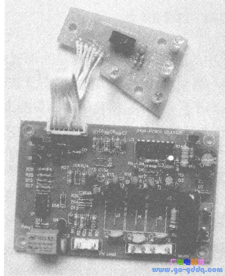
R23 and C11 form a delay protection circuit. Each time the power is turned on, the gear position is changed, or the high voltage output terminal of the negative ion module is short-circuited due to external reasons, the working current will rise from about 60 mA to about 100 mA for a short period of time, thus triggering the protection circuit by mistake. In order to avoid false triggering, the delay time of R23/C11 is set to about 2~3s, that is, only when the load current is continuously 2~3s exceeds 80mA, the protection circuit will be triggered. Appropriate adjustment of the value of R23~Cll can set the delay time arbitrarily, and has no effect on the performance of other circuits. The threshold of the protection current can be arbitrarily adjusted by replacing the resistance of the R19, which is very convenient. The actual installation photos are shown below.
Third, remote control circuit
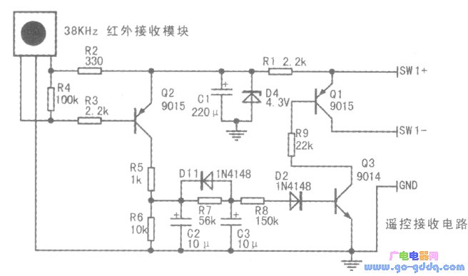
Remove the integrated infrared receiver without damage from the original machine (this type of receiver has been widely used in the infrared remote control circuit), the working voltage range is 2.4~6.5V, the working current is very small (300~500uA), facing the receiving window The left 1 pin is the signal output, the 2 pin is grounded, and the 3 pin is the power supply. The remote control circuit is as shown in the figure below. Connect SW+ to the SW1 positive pole of the main board (the (16) pin of Ul), and connect SW- to the negative pole of SW1 (the foot of (14) of Ul), and then connect the ground wire.
Yes, yes, no remote control! Because this circuit features no remote control, it can be replaced by any remote control of a TV or other electrical appliances, and will not affect the original function of the remote control.
Use any infrared remote control to align the receiving circuit, press and hold any button to put about Is, the receiving module 1 pin output follows the encoded negative pulse, so that Q2 also outputs forward encoding, and charges C2 through R5, C2 The voltage on the battery is charged to C3 through R7. The voltage on C3 is charged to about 1.4~1.5V, which makes Q3 turn on and Ql turn on, which is equivalent to SW1 pressing on the host, thus realizing remote control function. Once the remote control button is released, the voltage on C2 is quickly vented through the relatively small R6, and the voltage on C3 is also quickly vented through Dll-R6, ensuring that the remote unit circuit quickly returns to standby. Usually, when you watch TV remote control, you will not exceed Is when you press the button, and the fan control will be implemented when you press it long.
Fourth, the timing shutdown circuit
Without affecting the function, we make a little modification to the main control circuit, as shown in the following figure: The original function reset circuit is changed from the Q4 pin to the Q9 pin, so that the Q4~Q8 pins can be used to control 5 A timed gear. The timing IC adopts the new timing newcomer PT8A2513 in recent years. The advantage is that after reading the RC oscillation frequency, 32768 times of frequency division is performed as the timing time. It is not necessary to use a large timing resistor capacitor like the LM555 and other common timing ICs. For long time timing, the maximum timing of the RC parameters and circuit structure shown in the figure below can exceed 120s. Increasing the values ​​of Rt and Ca can also increase the timing time proportionally. To ensure the timing effect, the timing capacitor Ca is preferably a tantalum capacitor.
PT8A2513 is packaged in T0-94, just like a triode, facing the word surface, 1 pin grounded from the left, 2 RC oscillator circuit, 3 pin 2.0-5.5V power supply, 4 pin output high level, power supply is enough The high level output current of this pin can be greater than 12mA. When any one of U4's Q4~Q8 outputs a high level, on the other hand, the R5 and Zl circuits are powered by any diode of D15~D19, so that it outputs a 4.3V power supply voltage to U3, and U3's 4 feet when powering up. The output high level drives one of Ql~Q3 to turn on the low speed of the fan motor; on the other hand, it turns on Rtl~Rt5 respectively, one of the resistors and Ca constitutes the RC oscillator to provide clock to U3, and U3 internally performs 32768 points. After the frequency is timed, when the timing time is reached, U3 turns off the 4-pin output, thus turning off the fan motor and achieving the purpose of timing shutdown.
Do not worry that the positive terminal voltage of Rtl~Rt5 is higher than the power supply voltage of U3 and damage the IC. As long as U3 is powered on, U3 will continuously charge and discharge Ca, and the voltage across it will never be higher than the internal IC. The flipping threshold of the circuit, and there is a protection diode inside the IC, so even in the fault state, the voltage of the 3 pin will not be higher than the VCC+0.7V of U3, and the protection IC will not be damaged.
The PT8A2513 realizes one-time timed shutdown, and if U3 is changed to its sister product PT8A2512, it can realize cycle start: when it is in Q4 position, the whole machine will open at low speed for 20min, close for 20min cycle; and Q5 gear will cycle open. 40min, stop for 40min, especially suitable for sleeping. The Q4~Q8 gears do not need to be connected to the negative ion circuit. On the one hand, the circuit is too complicated. The Ql-Q3 pin output current is insufficient and the negative ion circuit and the timing circuit are driven. On the other hand, the timing is usually used. When you sleep late at night, long-term activation of negative ions is not good for your health. To say the shortcomings, the only drawback is that in order to simplify the circuit, only a certain wind speed can be fixed when starting the timed shutdown function (D20 in the following figure is connected to the slow speed).

Dongguan Tuojun Electronic Technology Co., Ltd , https://www.fibercablessupplier.com