At present, the types of clocks are more and more diverse, and their functions are becoming more and more abundant. However, most clocks are still traditional clocks, that is, fixed dials and hands. Their forms and functions are relatively single, and it is difficult to attract people. A rotating clock not only escapes the design of traditional clocks in creativity, but also caters to people's curious psychology, and the functions can also be diversified. Not only can the time and date be displayed, but even words can be displayed. The article designs a rotary clock based on the single-chip microcomputer that has the same second hand, minute hand, hour hand and dial scale as the traditional mechanical clock, and has the function of accurately displaying the instant time and the calibration time, and can be conveniently completed by an infrared remote controller.
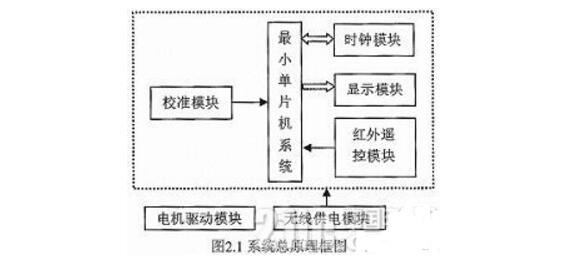
2, the overall design ideas and programsThe article intends to use 16 light-emitting diodes to simulate the clock on the dial, the rotation of a DC motor to achieve rotation; clock 1s source signal generated with the DS1302 clock chip; in order to ensure the stability of the clock face display using infrared to achieve; In order to facilitate the power supply to the rotating circuit board, wireless power is used; in order to be able to easily adjust the time of the rotating clock, it is proposed to use an infrared remote control. Therefore, the hardware module of the system is mainly composed of the following components: a display module, a wireless power supply module, a minimum single-chip system module, an infrared remote control module, a clock module, a calibration module, and a motor drive module. The system block diagram shown in Figure 2.1. Among them, the wireless power supply module uses the coil coupling to transfer energy to the single-chip microcomputer system, and the single-chip microcomputer system can work normally. The motor drives the microcontroller system to rotate rapidly; then the microcontroller reads the time of the clock module quickly, and sends the time information to the display module; the display module can control the corresponding LED to be on and off according to the time information, and then cooperate with the rotation of the motor. We can display clock. Since the entire clock is rotated at a high speed, the setting of parameters such as time and position is achieved using an infrared remote control module. The clock module provides accurate time for the entire system, while the calibration module is used to detect the starting point of the clock display.
The minimum system module of the single-chip microcomputer is composed of a single chip microcomputer (STC12C5A60S2), a clock crystal oscillator circuit, and a reset circuit. Among them, the reset circuit can realize two functions of button reset and power-on reset. The clock crystal circuit uses a 12 MHz crystal to provide the clock signal to the microcontroller. STC12C5A60S2 chip 31 pin (/ EA end) connected to the high level, so that it reads instructions from the internal program memory, in order to prevent the 31 pin accidentally output low level and burn the MCU, you need to connect a 31K resistor at the 31 pin .
3.2 Wireless Power Supply Module Analysis and DesignThe wireless power supply module consists of a sending module and a receiving module. The wireless transmission module is mainly composed of triodes B772 and 9013 and a primary coil. Which B772 working fever will be very severe, so to add heat sink. The main working principle of the circuit is based on Faraday’s law of electromagnetic induction, which first converts DC power into AC power, then sends energy through the primary coil, and the secondary coil finally senses power, and then completes power supply to the microcontroller through the corresponding circuit. Among them, the DC-to-AC part uses a self-oscillating circuit.
The principle of the wireless receiving module is as follows: First, the secondary coil is used to receive the energy sent by the primary coil of the sending module, because the sending module uses DC to AC to transfer the energy, so the secondary coil is the most induction to the AC. The power supply requirement of the single-chip microcomputer is direct current, so it must be rectified to become direct current, and finally by the 7805 regulator chip, used to output a stable 5V power supply, used to power the microcontroller.
3.3 Motor Drive Module Analysis and DesignThe motor used by the motor drive module is RF370 motor. When its operating voltage is selected at 5V, its rotation speed is between 2500 and 3100 rpm, and the current is only 20mA. It is very power-saving, and the rotation speed can meet the design requirements. The noise during rotation is also Small, so it is suitable to complete the design. The motor is connected to the wireless power transmission module through a 2-pin pin, and the 5V power supply powers the motor. Since the motor will store energy when it is working, it will be released when it stops working. In order to prevent the current released by the motor from burning out other circuits, a current limiting diode 1N4148 must be connected in parallel across the motor to function as a protection circuit.
3.4 Clock Module Analysis and DesignThe clock module consists of the clock chip DS1302 and its peripheral hardware circuits. DS1302 chip connects 32.768KHz crystal between 2 feet and 3 feet, DS1302 chip can get 1Hz standard signal after frequency division inside, offer the accurate time signal for the clock. 8 pin Vcc1 external 3V button battery, when the module is powered off, it allows DS1302 to continue to work to save time data; 1 pin VCC2 is also an external power supply 5V, when the dual power supply VCC2 as the main power supply to the module; 5 feet (/RST) is the reset / chip select terminal, used to control the DS1302 and external communications, and then connected to the P3.5 microcontroller pin; 7-pin (SCLK) is a serial clock input, providing a clock for data transmission, the foot and the microcontroller P3.7 pin connection; 6 pin (I/O) is the serial data input/output port (bidirectional). It is the data transmission pin for communication and is connected to the P3.6 pin of the microcontroller.
3.5 Calibration Module Analysis and DesignBecause the circular clock needs to rotate the LED to have a circular effect, it is necessary to use a sensor or an infrared tube to help determine the starting point position, and the display of the clock surface can also be fixed. This design uses an infrared tube, in which the infrared emitter is soldered in the wireless power supply module. The infrared receiver is connected to the P3.3 pin of the microcontroller. When the receiver tube receives the emitter signal, the resistance value will change. Too small, at this time P3.3 output low; when no signal is received, the receiving tube's resistance becomes very large, then P3.3 output high, that is, a decline along. P3.3 pin is the input pin of the external interrupt 1 of the one-chip computer, if this cut-off is set as the falling-edge triggering, then the falling edge will trigger the interrupt immediately, let the one-chip computer turn to carry out the starting point detection program, in order to realize the clock can be displayed normally and accurately. .
3.6 Display Module Analysis and DesignThe display module uses a row of LED lights to achieve the display clock effect. In this design, 16 LEDs are connected to the P1 and P0 pins of the microcontroller. D1 to D4 are green LEDs, and D5 to D16 are red LEDs. D1 is used to display the clock disc frame, D2 ~ D4 is used to display the dial scale, if the time is 12, 3, 6, 9 o'clock when the light is 3 lights, if it is the other time light two lights. D5 ~ D16 is used to achieve the dial pointer display, so that the display with the actual clock hands the same. Since the seconds hand is the longest in the clock, all seconds D5 to D16 are to be on; the minute hand is centered, so all D8 to D16 are lit when displayed; the length of the hour hand is the shortest, so only the D11 is lit when displayed. ~D16.
3.7 Infrared Remote Control Module Analysis and DesignThe infrared remote control module is composed of a remote controller and a receiving module. The remote controller used is the NEC protocol, and many household appliances use the infrared remote control. The receiving module uses the infrared integrated receiving head VS1838B, in which its 3 pins are connected to the power supply 5V, pin 2 is grounded, and pin 1 transmits the demodulated signal of the receiving head to the external interrupt pin 0 of the microcontroller (ie, P3.2). The use of interrupts did not allow the microcontroller to achieve infrared decoding.
4, software program analysis and designThe main idea of ​​program design is: First use a timer to generate a fixed time interrupt. The main task of interrupt execution is to increment a variable (named as Count) by one. This variable Count is important because it is determined based on its value. For example, when the motor rotates once, Count increases from 0 to 180, and one dial has 60 scales (ie, both seconds and minutes are 60). When Count increases by 15, the microcontroller will drive the LED to display the corresponding time. Added to 180, the 12 degrees are displayed. Therefore, the maximum value of Count is preferably a multiple of 60.
To solve the display of the clock hands, it is necessary to read the time of the DS1302 and then determine whether the Count reaches the corresponding Count value of seconds, minutes, and hours respectively, and if so, display the second hand, minute hand, and hour hand. For example, when reading the DS1302, the second value is equal to 20, since the count of rotation is 180 at maximum, and the total of one revolution is 60 seconds. Since 180/60=3, when Count is added from 0 to 180, it is added to 20*3. When =60, the microcontroller will light the second corresponding to the LED. The minute hand display principle is similar to this because one dial has 60 points. The algorithm of the hour hand is different because there are only 12 ticks on a dial. The algorithm for this time is (Hour*15)+(Minu/4). Because the dial is lapped, Count is added to 180, and the dial is only 12 points, so 180/12=15, plus the movement of the minute will affect the hour hand's movement. The conversion relationship is: (Minu*3) /12, Minu*3 is the corresponding Count value at this time, and it takes only 30 degrees to go 360 degrees, so 360/30=12. The corresponding Count value is (Hour*15)+(Minu/4). The requirement for this is that the timer's interrupt time must closely match the motor's rotation period, and the speed of the motor must be stable.
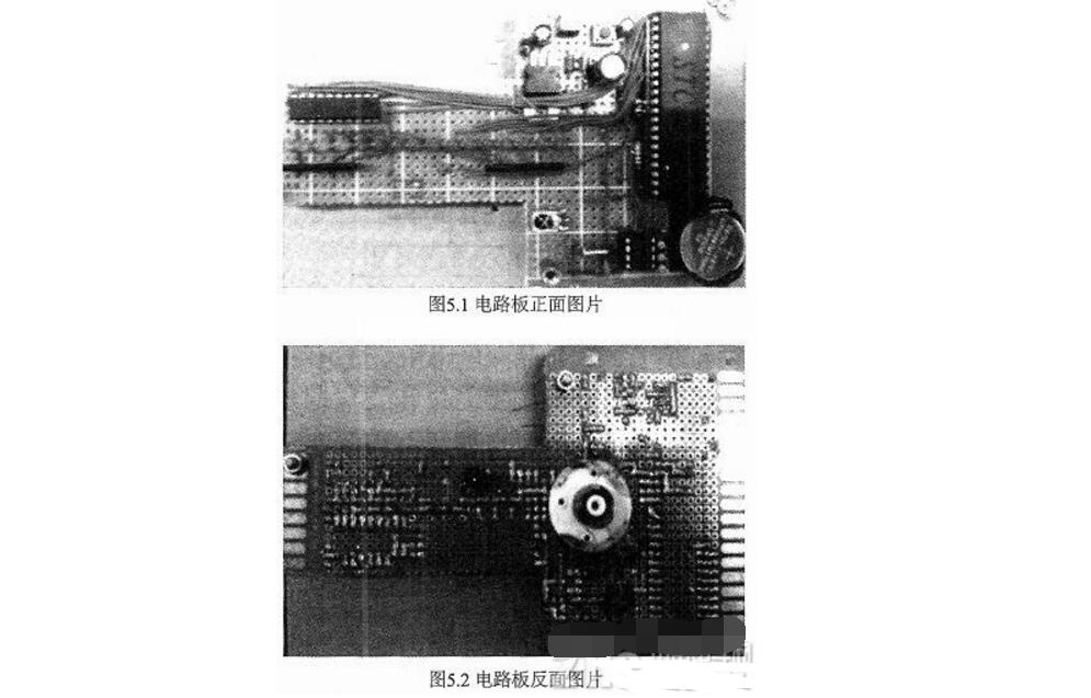
5, system function test analysisThe physical welding circuit is shown in Figure 5.1 and 5.2. Figure 5.1 shows the front side of the circuit board. The modules that can be seen above are the SCM minimum system module, display module, clock module, infrared remote control receiver module, and wireless power supply receiver module. Figure 5.2 is the reverse side of the circuit board. There is an infrared pair tube receiving module and a wireless power receiving coil. 2 screws are used for weighting.
Functional test results are shown in Figure 5.3, 5.4, 5.5 and 5.6. Figure 5.3 shows the real time 10:43:12 displayed after the system is powered on; Figure 5.4 shows the time after the clock normally moves 9 seconds after 10:43:21; Figure 5.5 shows the effect of adjusting the hour hand, adjusted from just 10 points to 1 point; Figure 5.6 is an adjustment of the minute hand effect chart, from just 39 minutes to 50 points. It can be seen from the test results that the electronic rotating clock operates normally, the time display is accurate, the dial display is stable, and the adjustment time function can also be achieved, so the design function meets the expected requirements.
The test results show that the rotary clock designed in this paper has the following advantages compared to other solutions on the market: 1 The dial (including the scale and pointer) shows a stable display without chattering; 2 The time is always accurate and not moving. After running for a period of time, it is wrong to run, the pointer is out of order, etc.; the brightness of the display is the same, and the display brightness is not uniform. Of course, there are also places where the function needs to be further improved. For example, the display date and text may be added to increase the content displayed on the dial, and the display mode may be switched by pressing keys.
This is the most competitive 15.6 inch Budget Business Laptop, comes with 2022 intel latest celeron cpu-N5095, J4125, etc . Of course, other Budget Working Laptop are also available.
For example, 15.6 inch i5 4th Budget Workstation Laptop for your mid-level task, 14 inch i5 10th Budget Laptop For 3d Modeling, 15.6 inch i7 5th Budget Laptop For Photoshop, or 15.6 inch i7 10th budget laptop for work, etc. Of course, there are other type device, like Android Tablet, 2 In 1 Laptop, Mini PC , All In One PC.
A thin, portable, light-performance laptop may be the ideal tool when people choose a business laptop, therefore just ask yourself 1.what jobs you mainly need this device to do, then choose the cpu and storage necessary, 2.if need fingerprint or backlight; 3. prefer type C charging? Or traditional DC is ok? 4. Does RJ45 webcam is important for you? 5. how many hours you need the laptop to work when do your main jobs?
6.Camera position, prefer on the middle of screen up? or is ok on the bottom of screen?
Budget Business Laptop,Budget Working Laptop,Budget Workstation Laptop,Budget Laptop For 3d Modeling,Budget Laptop For Photoshop
Henan Shuyi Electronics Co., Ltd. , https://www.shuyielectronictech.com