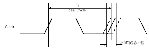
Jitter is a very critical concept of digital signals, especially high-speed digital signals. As shown in the figure below, the jitter reflects the time deviation of the digital signal from its ideal position.
The concept of jitter is known to everyone, but in fact it is very complicated to study carefully.
The understanding of the concept of jitter has several aspects that need attention: Frequency range of jitter: jitter is actually noise in time, and the frequency of its time variation may be faster or slower. Usually a jitter component with a frequency exceeding 10 Hz is called jitter, and a jitter component with a frequency less than 10 Hz is called wander. Wander reflects mainly the slow changes of the clock source over time, temperature, etc., affecting the absolute accuracy of the clock or timing signal. In communication or signal transmission, both the sender and the receiver both use a certain clock architecture to allocate and synchronize the clock. Slow clock drift can be easily tracked or compensated. Therefore, wander has little effect on the error rate of digital circuit transmission. The main concern of high-speed digital circuit measurement is high-frequency jitter. The ideal jump position: Jitter is a relative amount of time. How to determine the ideal jump position of the signal has a critical effect on the jitter measurement. For the measurement of clock signals, we usually care about whether the clock signals are exactly equally spaced. Therefore, this ideal position is usually the edge of an isochronous clock that is extracted from the measured signal. For the measurement of data signals, we The concern is that the signal jumps relative to its clock, so this ideal transition location is the transition location of its clock's active edge. For many high-speed digital circuits using embedded clocks, the situation is more complicated because there is no dedicated clock transmission channel. At this time, the ideal jump position usually refers to a specific clock recovery circuit (possibly also hardware It may be a valid edge of the recovered clock from the data. The method of measuring time deviation: due to the time deviation of signal edges may be due to various factors, random noise, and deterministic interference. Therefore, this time offset is usually not a constant value, but has a certain statistical distribution. In different applications, the result of this measurement may be measured by the RMS value, or may be measured by the peak-peak value. More complicated occasions will also decompose and estimate the components of this time deviation. Therefore accurate measurement of jitter requires a large number of samples and complex algorithms.
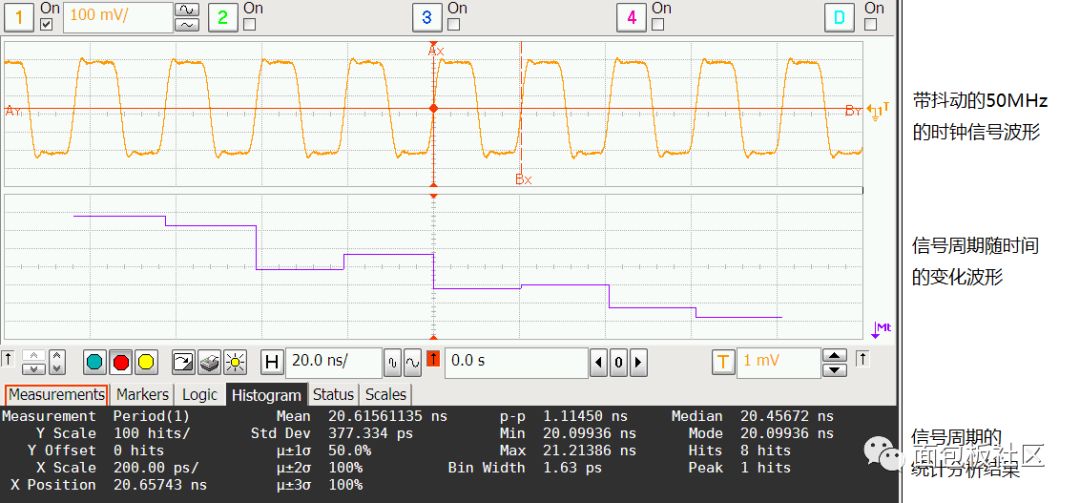
Jitter measurement method When measuring and measuring jitter, special attention should be paid to that even if the same signal is measured by different methods, the jitter measurement result obtained may also be different. Here are some A common jitter measurement item. Periodic jitter: For the clock signal, we are most concerned about whether its cycle is equally spaced. The ideal clock should be the same length of each cycle, but the cycle may change if the signal has jitter. Therefore, the average value, peak-to-peak value, RMS value, etc. of the signal period can be obtained by directly measuring and counting multiple periods of the clock signal. The following figure shows the result of periodic jitter measurement on a 50MHz clock signal with jitter. Although it is difficult for the human observer to observe subtle jitter in the signal from the original time domain waveform, we use the corresponding jitter analysis software. Can observe the signal cycle with time curve, as well as the signal cycle of the maximum, minimum, the peak value of the cycle change, the variance of the cycle change.
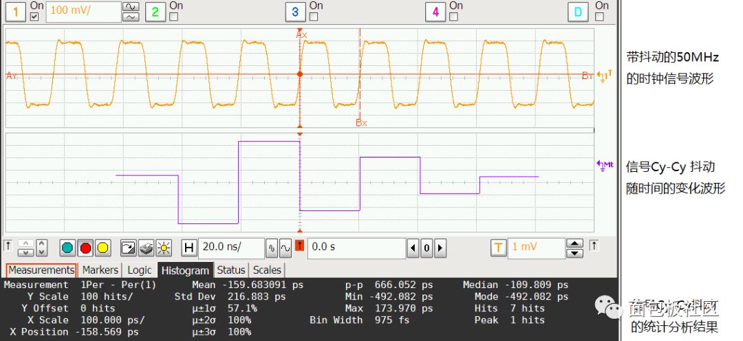
Cycle to Cycle Jitter: The above-mentioned cycle jitter can reflect the range of the clock signal cycle, but it does not reflect the speed of the cycle of the clock signal. For many synchronous digital logic circuits, if the cycle of the clock signal changes very slowly, even if the range of the cycle is very large, no fault will occur, but if the cycle changes rapidly, it may cause the circuit to malfunction. In order to measure the speed of changes in the clock cycle, it is sometimes measured as "period to period jitter." "Period-to-period jitter" is the subtraction of the adjacent two cycles of the clock signal. If a waveform captures 1000 cycles, you can get 999 "period-to-period jitter" measurements. The statistics of these measurement results can also be obtained the average value, peak-to-peak value, RMS value and so on. Some special applications (such as clock signals for DDR2/3) also define N-cycle jitter, which is the jitter variation of adjacent N clock cycles. The following figure shows the results of the Cyclic-Cycle jitter measurement and statistics for the same 50MHz clock waveform.
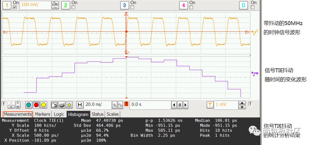
Time Interval Error: The so-called time interval error refers to the jitter of the edge of the measured signal relative to its reference clock. This reference clock can be a specific clock signal, or it can be recovered from the signal. For many high-speed serial digital signals, periodic jitter cannot be measured because it does not have a fixed cycle like a clock signal. Therefore, a large number of TIE jitter measurement methods are used. However, it should be noted that the time interval error is a relative measurement. How to select the reference clock and how to perform clock recovery will affect the measurement results of TIE jitter. Special attention must be paid to the measurement of TIE jitter. The following figure shows the analysis and statistical results of TIE jitter for the same 50MHz clock signal. A constant clock extracted from the signal using the minimum variance method is used as the reference clock.
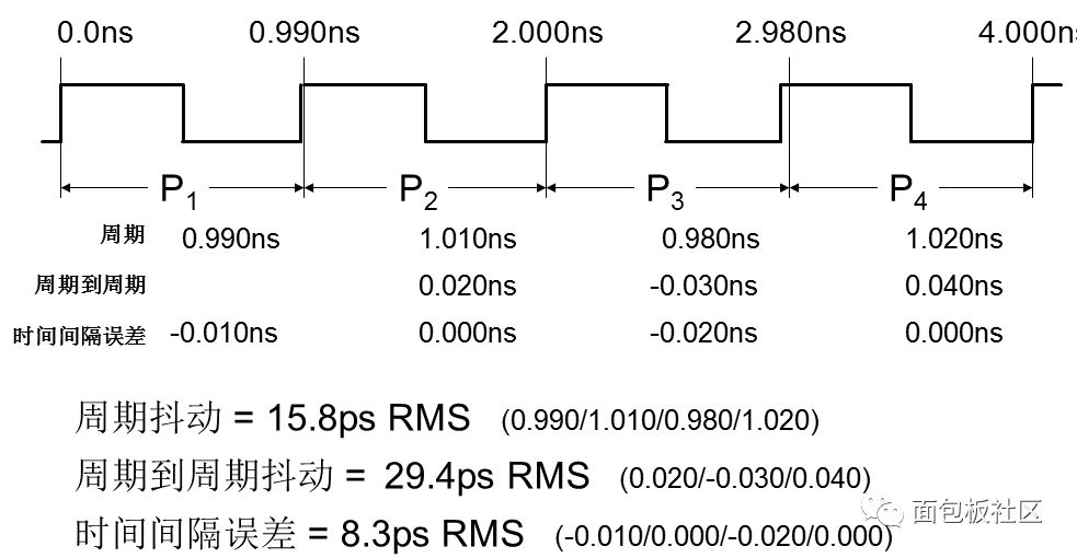
From the above example, we can see that for the same signal, measuring and measuring in different ways, the results obtained may be different. The following figure is another example. For the same jittered clock signal, the periodic jitter measurement, cycle-to-period jitter measurement, and time interval error jitter measurement are performed, and the results obtained may be different. Therefore, before a jitter measurement is performed on a signal, it is necessary to clearly identify the type of jitter. Otherwise, the physical meaning of the measurement result is unclear.
For more complex digital signals, in addition to the RMS value and peak-to-peak jitter, people will also be concerned about the different components of the jitter, because the jitter of different components is not the same for the impact of the circuit, and the corresponding response means Not the same. For example, many high-speed buses will further decompose and study Random Jitter, Periodic Jitter, and Inter-Symbol Interference Jitter of high-speed digital signals. Jitter is a very important concept of digital signals, especially high-speed digital signals. The faster the signal is, the shorter the bit period is, and the more stringent the requirement for jitter is. Jitter is a very complex problem. We will have time to specifically explain the concept and measurement of jitter.
Water-cooled capacitor is supercapacitor is a capacitor with a capacity of thousands of farads.According to the principle of capacitor, capacitance depends on the distance between the electrode and electrode surface area, in order to get such a large capacitance, as far as possible to narrow the distance between the super capacitor electrode, electrode surface area increased, therefore, through the theory of electric double layer and porous activated carbon electrode.
Water-Cooled Capacitor,Water-Cooled Power Capacitor,Water-Cooled Electric Heat Capacitor,Water-Cooled Electric Heating Capacitor
YANGZHOU POSITIONING TECH CO., LTD. , https://www.cnchipmicro.com