With the rapid development of computer and control technology, it has become more and more common for factories and mines to use host computers and PLC for centralized monitoring, and the technology is becoming more and more advanced. In this paper, taking the centralized control system of the belt conveyor in the coal mine in Hebei Danhou as an example, a PLC-based monitoring system for the belt conveyor in the coal mine is researched and developed, which is suitable for the automation needs of the current industrial enterprises. It is actually put into operation and has achieved good results. effect.
2 System design2.1 System overview
The single-hop mine belongs to Hebei Kailuan Mining Group. It is located near Beicheng Village, Yongquanzhuang Township, Yuxian County, Zhangjiakou City, Hebei Province. It is the center of the Zhangshi mining area. The mine has a geological reserve of 313.74Mt, a mineable reserve of 177.08Mt, and a design capacity of 150. 10,000 tons/year, the mine service life is 81.4, and it was officially put into operation in October 2006.
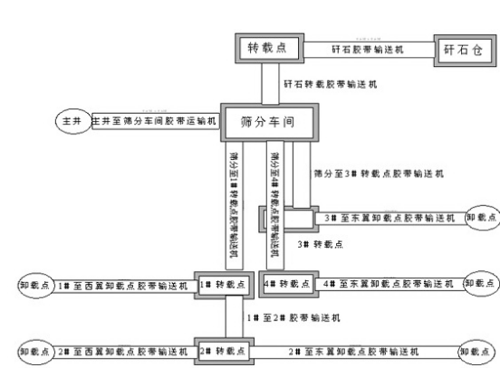
The centralized control system of the belt conveyor in the single-wait coal mine (see Figure 1) can be divided into two parts: 1. the screening workshop system; 2. the coal storage and loading system.
Among them, the screening workshop system includes the belt conveyor from the main well to the screening workshop as shown in the figure, the gangue transfer belt conveyor, the gangue conveyor belt conveyor, and the six gangue picking belt conveyors and three scrapers included in the screening workshop. Equipment; other belt conveyors belong to the coal storage and loading system.
In terms of design, the system is required to achieve two control modes: local control and centralized control. Centralized control can be divided into multiple control modes such as interlocking control and stand-alone control, which can be flexibly selected by the operator according to the actual situation on the spot to ensure that When the system is operating normally, it is flexible and easy to maintain. When the system fails or the communication is interrupted, it can be locally controlled to ensure the normal operation of the belt equipment, which improves the stability of the system.
2.2 System hardware
The whole system can be divided into two layers from top to bottom: centralized control management and local control management. The centralized control management layer is composed of two upper computers and a switch. In the operation of the system, the two upper computers are mutually redundant, and are directly interconnected with the field equipment through the switch, so as to realize the monitoring of the field equipment.
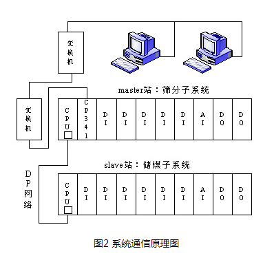
The local control management layer is composed of PLC, switch and tape protection device. PLC is the core of the entire control system. In this system, Siemens S7-300 is used. In practice, the coal storage subsystem and the sieve molecular system are mutually locked, therefore, a DP network can be constructed between the sieve molecular system and the coal storage subsystem (the communication principle diagram of the system is shown in Figure 2). Therefore, the PLC of this system adopts CPU315-2DP. When networking, the sieve molecular system is used as the master station, the coal storage subsystem is used as the slave station, and the Ethernet module CP341 is added to the sieve molecular system PLC cabinet to make the upper computer pass through the switch. It can be interconnected with field-level equipment to achieve centralized control. In addition, the belt conveyor is equipped with various protection devices such as deviation, coal stacking, cable switch, etc., so that the system can quickly respond when the belt conveyor fails.
2.3 System software part
The software part of this system is mainly composed of two parts: the configuration monitoring software of the upper computer and the programming software of the on-site PLC.
The programming software of the upper computer selects Intellution's IFIX3.5, which has the following characteristics.
a. Real-time library display: real-time display of all real-time points in the system;
b. Real-time remote control: select the control switch on the screen to issue remote control commands in real time;
c. Real-time and historical curves: can be set to display all recorded telemetry points in the system;
d. Real-time and historical alarms: alarms are divided into heavy alarms, medium alarms, and light alarms;
e. Inquiry of event and alarm records: event and alarm logs can be inquired on a daily basis;
f. Real-time printing of events and alarms: When an alarm event occurs, the event printer will print it in real time.
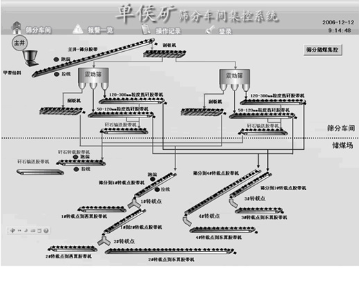
The upper computer monitoring software uses OPC to communicate with the on-site PLC, which can conveniently and flexibly obtain the telemetry and telesignal information of the on-site electromechanical equipment and its protection equipment, and realize remote control. The configuration software interface of the upper computer is shown in Figure 3.
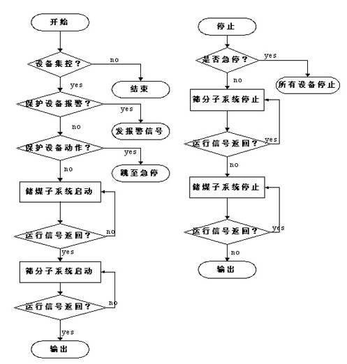
The programming software of the on-site PLC adopts Step7 of Siemens. When the PLC is in the "RUN" working mode, except for the power-on initialization, the other programs adopt the cycle scanning mode, which is called the "scanning working mode of the PLC". The execution process is shown in Figure 4.
3 System key technology3.1 The design of system-related communication programs
The main PLC control cabinet of this system (sieve molecular system PLC control cabinet) is installed in the low-voltage power distribution room on site. Due to the distance from the dispatching center and the serious electromagnetic interference on site, Ethernet and optical fiber transmission technology are specially adopted for this reason. Realize the communication between SIMATIC s7-300 PLC and the upper computer man-machine interface. The main PLC cabinet is equipped with an Ethernet module CP341 and an Ethernet to fiber switch.
In order to transmit and receive information correctly, there must be a set of agreements on the order of information transmission, information format, and information content. This set of agreements is called a statute or agreement. When designing the communication program, this system adopts the design idea of ​​modular programming and divides the program into several program blocks. Each program block contains program instructions for some equipment and tasks. Each functional area is divided into different blocks for programming. It is conducive to programming by multiple people at the same time, and it is also conducive to program debugging and troubleshooting. The PLC in the system needs to deal with multiple communication protocols, and the processing programs for each protocol are separately compiled and placed in different functional modules (FC). In the main program block OB1 of the PLC, through the call statement, the processing procedures of these protocols can be executed in sequence to achieve the purpose of communicating with these comprehensive protection devices or smart meters.
3.2 DP network configuration
Based on the closed relationship between the sieve molecular system and the coal storage subsystem, the sieve molecular system and the coal storage subsystem can be configured as a DP network. This makes the logical relationship of the system clearer, at the same time the system has good scalability, and also saves costs economically.
Regarding the configuration of the DP network, please refer to the relevant manuals of Siemens. In particular, the following points should be noted.
a. When configuring the master-slave station, the slave station should be configured first, and then the master station;
b. When configuring Hardware, the Consistency of the master station and the slave station need to be set to All;
c. When programming, there must be OB1, OB82, OB86, OB100, OB121 in OB1 of the master station;
d. Since the host computer performs read and write operations on the PLC when the system is running, SFC14 and SFC15 function blocks must be added to the program blocks of the master station and the slave station.
3.3 Lockout control of field equipment
In order to make up for the shortcomings of the field equipment's anti-error function and ensure safe production, all equipment on site should be locked and controlled.
This system has both mechanical lock and logic lock, which meets the requirement of "starting the equipment in turn against the coal flow and stopping the equipment in turn along the coal flow". Specific approach: mechanical lockout: string the normally closed point of the return signal of the device that is logically started first into the secondary control loop of the device after the start of the device; logical lockout: as shown in the flowchart, use the return signal of the device as the execution A prerequisite for a program.
(1) Through the use of large and medium-sized PLCs (such as Siemens S7-300), it can communicate with a variety of intelligent electronic devices, which facilitates the monitoring of field devices.
(2) Since the system was put into operation in October 2006, the amount of maintenance has been greatly reduced, and most of the faults can be directly displayed on the computer monitor, reducing the fault finding link. The system is simple to operate, easy to maintain, improve system safety, reduce operating costs, greatly reduce downtime, and improve economic benefits.
Networking Keystone Jacks.China Cat5e Coupler Jack,Keystone Jack Short Body manufacturer, choose the high quality Cat5e Jack Short,Keystone Jack Unshield, etc, included keystone jacks for CAT6A, CAT6, CAT5E, and CAT3
Keystone jacks are snap in modules used to mount low voltage electrical connectors into a keystone wall plate, patch panel, face plate or surface mount box.
Our Keystone Jacks are available in 10 different colors for easy color-coded installations.
RJ45 port editing
1. Origin:
2. The name RJ stands for the registered jack and is the USOC (universal service ordering codes) code of bell system. USOC is a series of registered sockets and their wiring mode, which are developed by bell system to connect the user's equipment to the public network. FCC regulations control the application of this purpose. The FCC (Federal Communications Commission) issued a document on behalf of the U.S. government to specify RJ11.
3. RJ11 is the common name of the connector developed by Western Electric Co. Its shape is defined as a 6-pin connecting device. Originally called wexw, where x means "active", contact or needle. For example, we6w has all six contacts, numbered from 1 to 6. The we4w interface only uses four pins, the outermost two contacts (1 and 6) are not used, and we2w only uses the middle two pins. For RJ11, the information source is contradictory. It can be a 2 or 4-core 6-pin connector. What's more confusing is that RJ11 is not only used to represent the 6-pin connector, it also refers to the 4-pin version.
4. RJ45 and RJ11: different standards, different sizes
5. Due to the different sizes of the two (RJ11 is 4 or 6-pin, RJ45 is an 8-pin connection device), it is obvious that the RJ45 plug cannot be inserted into the RJ11 socket. However, it is physically feasible (RJ11 plug is smaller than RJ45 jack), which makes people think that they should or can work together. It's not. It is strongly recommended not to use RJ11 plug for RJ45 socket.
â’ because RJ11 is not internationally standardized, its size, insertion force, insertion angle, etc. are not in accordance with the international standard connector design requirements, so interoperability cannot be guaranteed. They even cause damage to both. Since the RJ11 plug is smaller than the RJ45 socket, the plastic parts on both sides of the plug will damage the metal pin of the inserted socket.
RJ - 45 port is our most common port, it is our common twisted pair Ethernet port
Because twisted pair is mainly used as transmission medium in Fast Ethernet, RJ-45 port can be divided into 10Base-T network RJ-45 port and 100base TX network RJ-45 port.
Among them, the RJ-45 port of 10Base-T network is usually identified as "eth" in the router, while the RJ-45 port of 100base TX network is usually marked as "10 / 100btx". This is mainly due to the fact that most products of Fast Ethernet router still adopt 10 / 100Mbps bandwidth adaptive.
The left figure shows the RJ-45 port of 10Base-T network, while the right figure shows the RJ-45 port of 10 / 100base-tx network. In fact, the two RJ-45 ports are exactly the same in terms of the port itself, but the corresponding network circuit structure in the ports is different, so they can not be connected casually.
Definition of RJ45 interface pin signal
Ethernet 10 / 100Base-T interface:
1 TX + tranceive data +
2 TX - tranceive data -
3 RX + receive data +
4 N / C not connected
5 N / C not connected
6 RX - receive data
7 n / C not connected
8 N / C not connected
Ethernet 100base-t4 interface:
1 TX_ D1 + tranceive data +
2 TX_ D1 - tranceive data
3 RX_ D2 + receive data +
4 BI_ D3 + bi directional data +
5 BI_ D3 bi directional data
6 RX_ D2 - receive data
7 BI_ D4 + bi directional data +
8 BI_ D4 bi directional data
Note: RJ45 interface adopts differential transmission mode, TX + and TX - are a pair of twisted pair, which can reduce interference when twisted together.
Cat5e Coupler Jack,Keystone Jack Short Body,Cat5e Jack Short,Keystone Jack Unshield
ShenZhen Antenk Electronics Co,Ltd , https://www.atkconnectors.com