1 Introduction
This article refers to the address: http://
The non-contact IC card water-saving controller (referred to as water controller or water control machine) uses a non-contact IC card reader to control the water discharge, and implements no-charge management for water. It is a device that integrates metering function and control function. It is a kind of meter that uses modern microelectronic technology, modern sensing technology, non-contact IC card technology to measure water consumption and can carry out water data transmission and settlement transactions. New device. The place where the faucet flows can use the controller to achieve water saving. Such as: bathrooms, collective and individual apartments, boiling water rooms and other places. The device adopts the Mifare1 S50 non-contact IC card produced by the most common Philips company in China as a communication card, which has the advantages of small size, convenient carrying, waterproof and moisture proof, strong wear resistance, etc., and can be conveniently matched with a rice-selling machine, an access control system, The attendance system and the like are used together to form a campus card and a corporate card system.
2. Overall scheme and hardware design of water-saving controller based on non-contact IC card
2.1 Overall plan
It can be seen from the system block diagram of Figure 1. The water controller is mainly based on AT89C51 main control MCU, supplemented by RF interface module, flow measurement module, water control interface module, switching power supply circuit, digital display circuit, data storage circuit, bee. Sounder alarm circuit and other components.
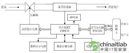
Figure 1 Non-contact IC card water saving controller system block diagram
As long as there is an IC card in the card reader reading range, the IC card is operated by the single-chip microcomputer to control the RF interface circuit, and the type of the IC card (user card or administrator card) is judged, and corresponding processing is performed according to the information content in the card. And according to the demand, the state of the solenoid valve (on or off) is controlled by the water control interface circuit, and the related information during the operation of the system is displayed through the digital display circuit or the relevant data is recorded into the data memory. In addition, the water meter sends a pulse signal through the flow sensor during the process of using water, and the single chip receives the pulse signal for calculation and processing, and then performs corresponding deduction processing on the IC card and displays relevant information through the digital display circuit, and performs real-time monitoring in the process of using water. If the balance of the IC card is too low, an alarm will be sounded through the buzzer. The various parts of the water controller operate in coordination to enable automated management of water.
2.2 Water controller hardware design
2.2.1 MCU module
The core MCU module of the water controller uses the built-in powerful and cost-effective AT89C51 microcontroller, which is a low-voltage, high-performance CMOS 8-bit MCU with 4k bytes of re-writable Flash read-only program memory. 128 bytes of random access data memory (RAM), using ATMEL's high-density, non-volatile memory technology, compatible with the standard MCS-51 command system. In addition, the external circuit of the MCU, such as: data memory uses AT24C01A as a non-volatile data storage (used to store setting parameters and consumption data, such as water price, cumulative consumption, etc.).
The digital display circuit can be driven by a 74HC164 digital display. In order to reduce the power consumption and heat generation of the device, a switching power supply is used as the power supply. The L4962E/A step-down PWM control switching regulator integrated circuit can be selected, which has adjustable output voltage, overcurrent protection, overheat protection and soft start. Features. The alarm circuit connects the buzzer to the basic I/O port of the MCU to achieve functions such as insufficient balance alarm. The water control interface circuit uses the basic I/O port of the AT89C51 single-chip microcomputer to output a control signal, which is used to control the opening and closing of the solenoid valve after being amplified. The water flow signal from the flow sensor is processed by the pre-circuit and converted into a series of voltage pulse signals that can be measured. These pulse signals can be captured by the timer of the MCU and recorded in real time by the interrupt service program. The user's water consumption, in turn, converts the water consumption into the amount that the user has to pay and controls the radio interface module to debit the IC card.
2.2.2 RF Interface Module
The module is mainly composed of MFRC500 chip and its antenna circuit.
1) Introduction to MFRC500
MFRC500 is a member of the high-integration card IC series for 13.56MHz contactless communication given by Philips in 2000. Utilizing advanced modulation and demodulation concepts, in accordance with the TYPE A protocol of the ISO/IEC 1443 standard, all types of passive contactless communication methods and protocols at 13.56 MHz are fully integrated. It has the following characteristics:
• The internal transmitter section can directly drive the near-operating distance antenna (up to 100mm) without adding active circuitry.
The Receiver section provides a robust and efficient demodulation and decoding circuit for ISO14443A compatible response signals.
The digital part handles ISO14443A frame and error detection (parity & CRC); in addition, it supports the fast CRYPTO1 encryption algorithm for verifying the MIFARE family of products. The convenient parallel interface allows direct connection to any 8-bit microprocessor, which provides great flexibility in the design of the reader/terminal.
The hardware circuit design of the RF interface module is shown in Figure 2.

Figure 2 RF interface module hardware circuit diagram
2) Microcontroller and MFRC500 interface circuit design
The interface between the MCU and the MFRC500 adopts the interface mode of the independent read/write multiplexed address bus. The parallel port (P0~P7) of the MFRC500 is connected to the P0 port of the MCU, the chip select signal NCS is connected to the P2.7, and the MFRC500 is interrupted. Connected to INT1 of the microcontroller, the reset pin RSTPD is connected to P1.2 of the microcontroller. In addition, in this mode, A2, A1, and A0 of MFRC500 are connected to GND, VCC, and VCC, respectively, to ensure that the input levels of A2, A1, and A0 are low, high, and high, respectively.
3) Antenna circuit design
The antenna circuit consists of four parts, namely an EMC (electromagnetic compatibility) low-pass filter, a receiving circuit, an antenna matching circuit, and an antenna.
The EMC low pass filter consists of L0 and C0. The Mifare system operates at a frequency of 13.56 MHz. This frequency is generated by a quartz crystal oscillator for driving the MFRC 500 and the fundamental frequency of the 13.56 MHz energy carrier that drives the antenna. This produces a 13.56 MHz transmit power and emits higher harmonics. International EMC regulations define the magnitude of the transmitted power in the broadcast band. Therefore, the output signal must be properly filtered. The receiving circuit is composed of R1, R2, C3, and C4. The internally generated VMID potential is used as the input potential of the RX pin. In order to provide a stable reference voltage, a capacitor C4 to ground must also be connected to the VMID pin. The receiver of the reader is connected to a voltage divider between the RX and VMID pins. A series capacitor is used between the antenna coil and the voltage divider. The components of the EMC low-pass filter and receiver circuit are listed in Table 1 below:
The antenna matching circuit is composed of C1, C2a, C2b. Here, it is designed as a matching circuit that directly matches the antenna. The value of each component depends on the electrical characteristics of the antenna and the influence of the environment.
Accurate calculation of the inductance of the antenna coil is not feasible. It can be estimated by the following formula that the antenna is generally designed to be circular or rectangular.
Table 1 Values ​​of EMC filter and receiver circuit components
Where, I1 is the length of one turn of the conductor loop; D1 is the diameter of the wire or the width of the conductor on the PCB; K is the shape factor of the antenna (circular antenna K=1.07, rectangular antenna K=1.47); N1 is the number of turns.
3. Software design
The controller adopts the Mifare 1 S50 type contactless IC card, and the IC card is set as the user card and the administrator card. The user card is the card for buying water; the administrator uses the card to set parameters and read the consumption amount of the water controller. The administrator card should be set on the PC with the system management software before use. The administrator signature is written in a partition of the IC card to distinguish the card type.
3.1 The overall flow of the water controller
The overall flow chart of the water controller is shown in Figure 3.
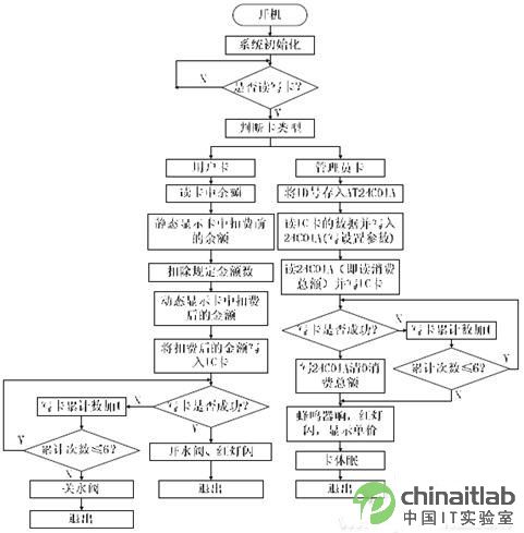
Figure 3 overall flow chart of the water controller
System initialization includes initialization of the microcontroller, read 24C01A operation, display processing, and MFRC500 initialization. The 24C01A operation is read to display the unit price. The initialization of the MFRC500 is to set the internal registers of the MFRC500. When an IC card is close to the reader, the system identification code is first read (determining whether the card is suitable for the system), and then the card type is determined and the corresponding user card or administrator card processing flow is entered. In the process of processing the user card and the administrator card, it is considered that a bad card may occur in the long-term use, and thus the process of limiting the number of times of writing the card is set, and if the card is unsuccessful after 6 times, the card is exited and alarmed.
3.2 reader and IC card communication process
The flow chart of the communication between the reader and the IC card is shown in Figure 4 below.
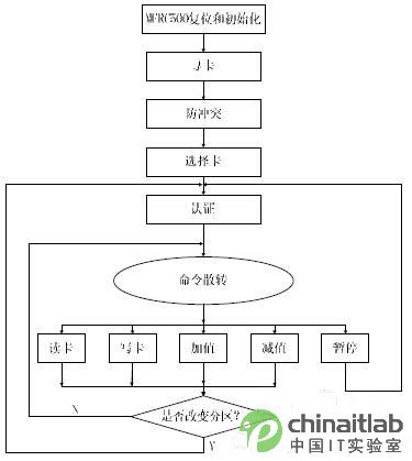
Figure 4 reader and IC card communication flow chart
First, the MFRC500 is reset and initialized after power-on. When the IC card is within the read/write range of the reader, the reader sends a request command to the IC card, and the ATR (reset response message) of the IC card is started. The 2BIC card type in the IC card is transmitted to the reader, and the first communication communication between the IC card and the reader is established. If there are multiple IC cards in the working range of the reader antenna, the anti-collision module will start. The reader first communicates with each card to obtain the serial number of each card, and the serial number of the card is unique. According to the serial number of the IC card, an IC card is selected for operation, and is not selected. The IC card is in a waiting state. The serial number is stored in block 0 of the IC card for a total of 5B, where 1B is the check byte (CRC code) of the serial number. After completing the above two steps, the reader must also select the IC card, and the reader will receive the capacity byte (stored in block 0) transmitted from the selected IC card. When the reader receives this byte, it can perform password authentication on the IC card. The password authentication of the non-contact IC card is divided into three steps, which is called triple authentication. Only after the triple authentication is passed, the partition of the IC card can be read and written. The Mifare1 type IC card has a total of 16 partitions, and each partition can be set with its own password, without mutual interference. If you change the partition, you must also re-do the triple authentication with the key of the partition.
4 Conclusion
This paper introduces a design scheme of a non-contact IC card water-saving controller, carries on the overall design of the system scheme, and designs the RF read-write module in detail, and gives the hardware circuit diagram of the RF read-write module. At the same time, the software design flow of the system is given, as well as the communication flow of the electronic tag and the reader. As a part of the campus card and enterprise card system, the non-contact IC card water-saving controller is more and more deeply rooted in people's lives, providing people with automated services for the utilization and management of water resources, bringing convenience to people's lives. .
Hp Laptop 15-Da 15-Db,Hp 250 G7 Keyboard,Hp 15-Da Base Enclosure,Hp 15 Base Enclosure
S-yuan Electronic Technology Limited , https://www.syuanelectronic.com