Adopt GPS / GSM technology to develop anti-lost personal positioning system. The system is used to search and protect lost children or elderly people with intellectual disabilities. The system uses GPS positioning technology to obtain the position of the protected person, determine whether it is out of the safe area, and can send its position information to the user through the GSM network.
Users can set the working status of the system through the GSM network. The internal control of the system is completed by the single-chip microcomputer, which receives GPS data and commands from the user and gives corresponding processing after analysis. The positioning accuracy of the system is within 10 meters, and the user can be notified of the position of the protected person in time.
0 Preface
This design uses the GPS system to obtain the location of the lost child or the elderly with intellectual disabilities, and sends the location data to the user through the GSM network. Since the short message service is charged according to the number of short messages sent, as long as the short message is limited to 140 bytes at a time But, this data length is enough to transmit GPS positioning information. The protection of children and the elderly can be achieved in a cheap way. The system uses the widely used and cheap AT89C52 single-chip microcomputer, SIRF third-generation GPS receiver module and GSM module TC35i design.
1 Personal positioning system hardware design
The personal positioning system is mainly composed of four parts, namely GSM module, GPS receiver module, single-chip microcomputer control circuit and power supply circuit. The GPS module is responsible for receiving positioning data; the GSM module sends and receives short messages under the control of the single-chip microcomputer; the single-chip microcomputer control circuit analyzes the GPS positioning data and makes corresponding processing according to the user's settings. The power circuit is produced by 7805 and LM294lCS as + 5V and + 4.2v DC voltage, respectively. + 5V DC voltage is used as the working power supply of the single-chip computer and GPS module, and + 4.2V DC voltage is provided to the GSM module. The structural block diagram of the system is shown in Figure 1.

1. One-chip computer control circuit
The system selects the widely used AT89C52 microcontroller as the MCU. There are 8k bytes of Flash program memory and 1256 bytes of RAM inside. There is only one universal asynchronous serial port inside the microcontroller. In order to be able to communicate with GPS and GSM modules at the same time, the microcontroller requires two serial ports. So this system uses the serial port expansion chip GM8123 to realize the simultaneous transmission and reception of GPS data and GSM data. The interface circuit of the one-chip computer and GM8123 module is shown as in Fig. 2.
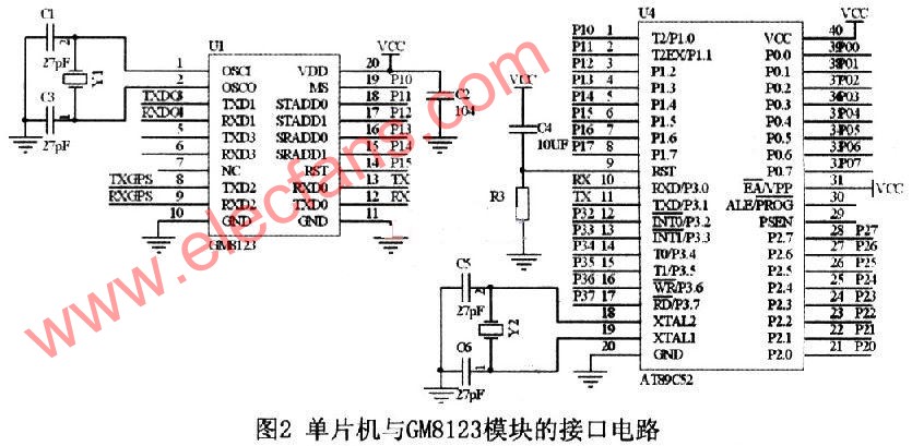
When the serial port expansion chip GM8123 works in multi-channel working mode, the mode control pin MS = 0. Multi-channel mode allows 3 sub-serial ports to work in full-duplex at the same time. In this working mode, the address lines STADDl ~ O of the chip are input ports, and the MCU controls the sub-serial port that wants to send data. The address lines SRADDl ~ 0 are output ports, which are used to return the sub-serial port address of the received data to the MCU. Through the control of the chip, the single chip microcomputer can communicate with the GPS module and the GSM module in full duplex at the same time.
1.2 GSM module
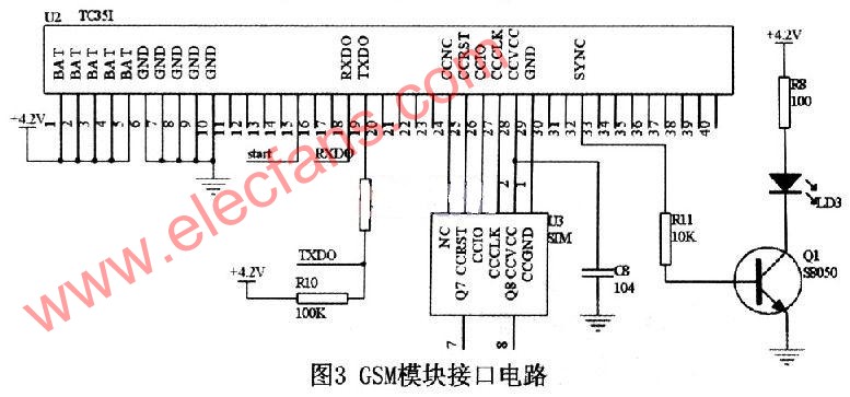
The GSM module is responsible for transferring information between the protected object and the monitoring user. This system uses the German GSM module TC35i of Siemens Industry. The TC35i module is an industrial-grade GSM module that works in GSM900 and GSMl800 dual frequency bands and supports Chinese short messages. The data interface (CMOS level) of TC35i can transmit commands and data in both directions through AT commands. It supports SMS (short message) in Text and PDU format. The GSM module interface circuit is shown in Figure 3.
1.3 GPS module
The GPS module used in this system is SIRF starâ…¢, the third-generation high-sensitivity lead-type GPS receiver module of SIRF. The positioning accuracy of the chip is within 10m, and it can track up to 20 satellite channels simultaneously. There is a rechargeable battery inside, which can save ephemeris data for quick positioning. The serial port data format is TTL level data output, the communication rate is 4800 communication baud rate, and GPS full data is output once per second. The GPS antenna of this module adopts MMCX interface, the data line interface is a 6-wire connector, cable output, simple to use, in general, only three output wires are needed, and the first pin is connected to a 3.5-5.5V DC positive power supply , The fifth pin is the power ground, the second pin is the GPS output line, it is a serial signal of TTL level, the high level is greater than 2.4V, the low level is less than 0.4V, the output drive capacity is 2mA, you can directly Interface with MCU. If only the default settings are used, the microcontroller can only read data from this module. 2 System software design
2.1 Reception of GPS positioning data
By default, the GPS receiving module SIRF star III outputs positioning data once per second, usually in the reduced data format $ GPRMC. Important information such as minutes, seconds, milliseconds, whether the positioning data is valid or invalid. The statement format is as follows:
$ GPRMC, <1>, <2>, <3>, <4>, <5>, <6>, <7>, <8>, <9>, <10>,
Since you only need to know the location information, in actual applications, you only need to read <1> to <6>.
<1>: represents UTC local time. The format is "hour, minute and second", and the hour, minute and second are two digits.
<2>: represents working status. "A" indicates that the data is available, "V" indicates that the receiver alarms, and the data is not available.
<3>: represents latitude data. The format is "degree, degree, minute, minute. Minute, minute, minute".
<4>: represents the latitude hemisphere, which is "N" or "S".
<5>: represents longitude data. The format is "degree, degree, minute, minute. Minute, minute, minute".
<6>: Represents the longitude hemisphere, "E" or "W".
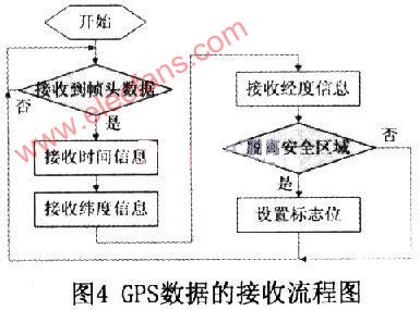
After reading the latitude and longitude data, the software analyzes the current position to determine whether the current position is in a safe area set by the user. The judgment method is to calculate whether the preset safe activity radius is exceeded according to the latitude and longitude of the activity center point set by the user and the current latitude and longitude of the protected object. Set the corresponding flag according to the judgment result. The flow chart is shown in Figure 4.
2. 2 GSM module control and short message processing
The single chip microcomputer can control the GSM module TC35i through the AT command, sending text messages commonly used TEXT and PDU mode, using TEXT mode to send and receive SMS codes is simple, it is very easy to implement, but the disadvantage is that it does not support Chinese text messages; and the PDU mode not only supports Chinese text messages, but Send English text messages.
The choice of the two modes is determined by AT + CMGF. When AT + CMGF = 0, it is PDU mode. When AT + CMGF = 1, it is TEXT mode. When the SMS to be sent contains Chinese characters, the sending mode should be set first. For the PDU mode, the Chinese characters are converted into 16-bit Unicode codes and then sent. For numbers, 8-bit binary 0s are added before the ASCII code, and they are sent after 16 bits are enough. When the mobile phone receives a text message, the program determines whether the received text message has Chinese characters, and then decides which mode to use to read the text message.
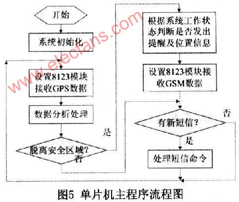
The MCU mainly transmits two types of information through the GSM module: one is to receive the user's setting and request commands and give a reply after processing; the other is to send a reminder to the user when the MCU determines that the protected object has left the safe area And location information.
The format of user settings and request information is shown in Table 1. The main program flow chart of the single chip microcomputer is shown in Figure 5.
When the user receives the positioning SMS, he can determine the location of the protected object. Users can query the geographic location corresponding to the latitude and longitude data through Google Maps through a smartphone or computer.
3 Conclusion
After testing, the system can achieve positioning within 10m accuracy, and can provide positioning services to users according to user settings. The system is easy to operate, suitable for protecting the safety of elderly and children with intellectual disabilities, and has good practical value.
Servo Cable is suitable for continuous moving occasions, double shielding effect strong anti-interference ability, signal transmission line and power connection line integration, saving installation space to reduce their own weight, maintain the reliability and stability of work, Widely used in control motors, executive motors, machine tool manufacturing, automobile manufacturing, heating and air conditioning systems, complete equipment installation engineering, paper industry, refrigeration equipment, office automation equipment, and data processing systems and other occasions.
Servo Encoder Cable,Incremental Encoder Cable,Siemens V90 Cable,Motor Application Encoder Cable
Kunshan SVL Electric Co.,Ltd , https://www.svlelectric.com