With the development of electronic information technology, smart cards (RFID/xinpin/zhinenka/'target='_blank'" IC cards) can be seen everywhere in life. Radio frequency identification cards (RF cards, RFID cards) are gradually replacing traditional contact IC cards, becoming a new trend in the field of smart cards. Due to the successful combination of radio frequency identification technology and IC card technology, the RFID card solves the problem of passive (no battery in the card) and contactless, and therefore has the advantages that the magnetic card and the contact IC card are incomparable. The RFID card consists of an IC chip and an inductive antenna. It is completely sealed in a standard PVC card with no exposed parts. The student attendance system is designed to use radio frequency identification (RFID) technology to perform functions such as attendance and recording for students.
Attendance and record management of students' attendance by means of name, magnetic card and contact IC card are time-consuming and easy to interfere with each other; non-contact RFID student attendance system realizes the use of radio frequency identification technology for student attendance management It is convenient, fast and time-saving. The student attendance system consists of a transponder and a reader, wherein the transponder consists of a tag (ie card), the reader (reader) consists of a radio frequency card base station device U2270B and its supporting circuit, the main control device MCU and its supporting circuit and periphery Interface circuit (keyboard, LCD, clock and serial port module), as shown in Figure 1.
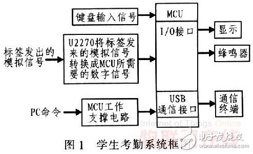
The student attendance system works as follows: The MCU works in a low-power state, and the tag is dormant because there is no energy. When the IRQ button on the keyboard is pressed, the MCU is awake and the U2270B is activated to start working. The two antenna terminals of the U2270B transmit energy to the outside through the coil. When there is a tag close to the coil, the tag gets energy to start working, and sends the information stored in it to the input end of U2270B. After U2270B is converted, the information is sent to the output port and sent to the MCU. After receiving the information, the MCU converts it. Make identifiable data and send it to the LCD. This paper focuses on the radio frequency card base station device U2270B and its supporting circuit design in the attendance system.
1 RF card base station device U2270B and its circuit designU2270B is a base station device produced by ATMEL. It is a non-contact working base station for reading and writing IC cards. It consists of an oscillator, an antenna driver, a power supply circuit, a frequency adjustment circuit, a low-pass filter circuit, and a high-pass filter circuit. The output control circuit is composed of parts.
1.1 RF card base station device U2270B RF frequency
The U2270B base station's RF frequency is required to be in the range of 100 to 150 kHz. At a frequency of 125 kHz, the standard data transmission rate can reach 5000 baud. It can be used in Manchester and two-phase modulation. The base station's operating power supply can be a car battery or other 5 V standard power supply. The U2270B features fine-tuning, a good compatibility with other microcontrollers, low power consumption in low-power modes, and power output for IC cards. The internal structure of the U2270B device is shown in Figure 2.
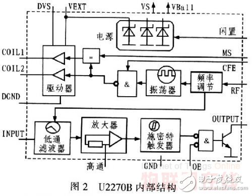
The U2270B's RF frequency is adjusted by adjusting the size of the RF lead pin in the internal structure of the U2270B. The internal oscillation frequency can be fixed at a specific frequency (typically 125 kHz), and then amplified by the antenna driver at the antenna. A radio frequency field of a specific frequency is formed nearby. When the transponder enters the radio frequency field, an induced potential is generated at the antenna end of the tag due to electromagnetic induction, and the induced potential is also a source of energy for the tag. Writing data to the transponder adopts the field gap method, that is, the shoulder vibration and the stop vibration of the oscillator are controlled by the "0" and "l" of the data, and the RF field with narrow interval is generated by the antenna, and the different field widths are respectively The data "0" and "l" are represented, thus completing the process of writing data transmitted by the base station to the tag.
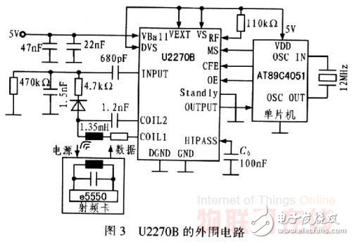
Field control is achieved by controlling pin 6 (CFE) of the device. The load modulation of the transponder produces a weak amplitude modulation on the base station antenna, so that the tag-modulated data stream can be recovered by demodulating the base station antenna voltage by a diode. The peripheral circuit of U2270B is shown in Figure 3.
1.2 RF card base station device U2270B support circuit
1.2.1 Power Module
The U2270B's VS (power supply) supplies power to the internal circuitry, and VEXT provides voltage to the antenna and external circuitry. There are three design modes for the U2270B base station power supply: the first one is single voltage supply, that is, the pins DVS, VEXT, VS, VBall use 5 V power supply; the second type is dual voltage power supply, that is, the pin Vs uses 5 V voltage, The pins DVS, VEXT, and VBall use 7 to 8 V; the third is battery voltage supply, the pins VEXT and Vs are supplied by the internal battery, and the pins DVS and VBall use 7 to 16 V external voltage. Power mode, U2270B's low power mode is available. The student attendance system is designed using a second power supply solution.
1.2.2 Frequency setting
The frequency setting is the antenna driving frequency of the U2270B output, and the transmitting frequency of the antenna terminal coil is ultimately determined by the resistance and capacitance of the coil circuit. The closer the frequency is to the transmitting frequency, the stronger the transmitting power. The U2270B's antenna drive frequency can be set by itself. The system design frequency setting is determined by the current value flowing into the RF terminal, and Vs is supplied by the internal power supply, so it can be set by changing the resistance value between the Vs terminal and the RF terminal.
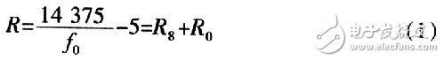
After calculation, the set resistance values ​​are R8=68 Ω and R9=43 Ω, so the RF frequency is 125 kHz.
1.2.3 Antenna Module
The antenna module designed by this system only involves capacitors, resistors and coils, but the selection of each component is more accurate. From the Coil1 and Coil2 ports of the U2270B, an IC series resonant frequency selective loop is formed by capacitors, resistors and coils. The function is to select useful signals from a plurality of frequencies to filter out or suppress unwanted signals. The resonant frequency is known from the resonant angular frequency of the series resonant circuit:

When the pulse from Coil1 and Coil2 satisfies the frequency setting requirement, the series resonant circuit starts to generate a higher resonant voltage VL=QVs across the loop. Among them, Vs is the output voltage of Coil1 and Coil2 of U2270B, and the resonant voltage VL at both ends of the coil may generally be between 200 and 350 V, so the capacitor withstand voltage at both ends of the coil is high and the thermal stability is good, so the resonant circuit The capacitance requirements are relatively high. When the resonant voltage reaches a certain value, the transponder is powered by the induced electric field. When the transponder enters the induced electric field, the internal circuit of the transponder performs very weak amplitude modulation on the basis of the resonant pulse, which is then read by the U2270B. Q is the quality factor of the resonant tank and is used to describe the ratio of the energy stored in the loop to its energy consumption:

In this design, the frequency of the transponder tag is 125 kHz, and the inductance L of the coil is about 1.35 mH, so that the capacitance of the capacitor C can be calculated by the equation (3). In addition, by adjusting the resistance R (note that the coil also contains a certain resistance) to adjust the quality factor Q, change the resonance voltage, and improve the read and write distance.
1.2.4 Data Entry
The data input here is the data read back from the antenna loop by the U2270B. The base station reads the carrier-modulated signal from the transponder. It is capacitively coupled to the INPUT input through the C7 capacitive Coupling. After passing through the low-pass filter, amplifier, Schmitt trigger, etc., the output is demodulated at the OUTPUT terminal. signal of. The cutoff frequency of the low pass filter is determined by fosc. The value of the coupling capacitor C7 of the pin INPUT and the decoupling capacitor C6 of the pin HIPASS determine the high-pass characteristics of the demodulation circuit, which helps to further filter out unwanted and interfering signals. The capacitance values ​​of C6 and C7 vary with the data transmission baud rate of the RF card. The student attendance system is designed with a baud rate of focs/32, where C6 and C7 are 100 nF and 680 pF, respectively.
The relationship between C6 and the lower cutoff frequency fCVT:
Where, Ri = 2.5 Ω.
It should be noted that the signal output from the OUTPUT terminal is only demodulated and is not decoded. Decoding needs to be done by microcontroller programming.
2 U2270B module software designThe U2270B module provides high-level calls to the main four functions, which are initialization function, stop function, open function and decoding function.
1) The initialization of U2270B initialization function U2270B is mainly to provide the necessary control port of U2270B to meet the condition level. Since decoding is not started immediately, U2270B should be stopped at the same time, and the default is 125 kHz decoding.
2) U2270B stop function Considering the low power consumption and specific functions of the system design, the decoding function is called only when the photoresistor interrupt is enabled or the "IRQ" key is pressed. In other cases, the U2270B is normally idle.
3) Turn on the U2270B function When the “Start Class†button is active, the photoresistor interrupt is enabled, or the “IRO†button is used to wake the reader from low power mode, and the U2270B is in operation.
4) The decoding part of the U2270B decoding function is completely implemented by the software program, and the received pulse is decoded by input, which is also the inadequacy of the U2270B.
3 SummaryThe core of the student attendance system design is the RF card reader, and the key of the RF card reader is the RF card base station device, which mainly performs data modulation, transmission and RF reception and data demodulation tasks. From the advantages of easy use of RFID cards, fast transaction speed, easy maintenance and long service life, RFID cards are gradually replacing the widely used contact IC cards. The student attendance system designed here realizes convenient, fast and time-saving student attendance management functions.
Multi function remote manual pulse generator for control of all axes.
Manual Sensor,Miniature Optical Kit Encoder,Rotary Encoder With Led Ring,Optical Quadrature Encoder
Yuheng Optics Co., Ltd.(Changchun) , https://www.yuhengcoder.com