Scanning probe microscopy (STM) is the most important tool in the development of nanotechnology. He is based on the theory of tunnel penetration in quantum mechanics. The core is an atomic-scale tip that scans the surface of a metal sample and has a bias voltage between the samples. When the distance between the sample and the tip is very close, electrons can be transferred from the tip to the sample or from the sample to the tip by tunneling to form a tunneling current. The magnitude of the tunnel current is inversely exponential with their spacing [1]:
IâˆB exp(-KS)(1)
Where: I is the tunnel current between the sample and the tip; B is the coefficient related to the bias between the sample and the tip; K is the coefficient related to the mass of the free electron and the effective average barrier height; S is the sample and Tunnel current between the tips.
The basic structure of a scanning tunneling microscope can be divided into three parts: a head system, an electronic system, and a computer system. The scanner in the head system is a critical component. The quality of the scanner determines the accuracy of the tip and sample spacing, which determines the quality of the STM image. Currently, tubular PZT piezoelectric ceramic materials are generally used. The scanner can perform nano-scale precision movement in three directions: x, y, and z. The xy scan voltage generator generates a scan waveform such as a triangular wave, and controls the scanner to scan the sample line by line. The tip is fixed on the scanner and moves with the scanner. Under the action of the tip and sample bias voltage, tunnel current is generated when the tip and sample are close enough. The sensitive current amplifier detects the tunnel current and converts it to a voltage, which is then compared to the current set point. The result of the comparison reflects the deviation between the tip and sample spacing and the setpoint. A proportional-integral controller is usually used in the STM electronics system as a feedback circuit to adjust the z-direction movement of the scanner to keep the tunnel current constant. The distance between the tip and the sample in the z-axis direction reflects the fluctuation of the surface height of the sample. . This is the constant current mode of STM [2].
At present, there are many manufacturers in China that produce scanning tunneling microscopes. The internal electronics part is basically composed of DSP chips as the core and external high-precision A/D or D/A peripheral components. Due to the complexity of the structure and function of the DSP chip, it is inconvenient to use and learn. The following introduces a PIC16C65 mid-range microcontroller produced by MICROChip, with a peripheral 16-bit A/D converter MAX195 and D/A converter AD1866. The electronic system of the scanning tunneling microscope of the device.
2 PIC16C65 microcontroller and MAX195 interfaceMicrochip's PIC family of microcontrollers features a Harvard dual-bus architecture that uses a reduced instruction set and instruction pipeline architecture that runs very fast and can completely replace the DSP to operate [3]. The MAX195 is a 16-bit serial output A/D converter from MAXIM that is fast, low power, and self-calibrating. The MAX195 is primarily used for tunnel current acquisition. The connection between the MAX195 and the PIC16C65 and the peripheral connection of the MAX195 are shown in Figure 1.
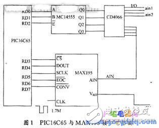
In Figure 1, the PIC16C65 microcontroller is connected to the MAX195 and MC14555 through the 7 pins of the general I/O port D port. The A/D conversion process is controlled by the PIC16C65 program. This program uses asynchronous read mode, that is, read data after 16-bit data conversion is completed. At the beginning of the conversion, first set /CONV to low level to start the conversion. After the conversion starts, the MCU continuously checks whether the level of the EO C pin is low. If the conversion is low, the MCU has 16 serial outputs through the RD5 port. The pulse is sent to the MAX195, and the 16-bit data obtained after the conversion is sent to the PIC microcontroller bit by bit through the RD4 port for reading and processing.
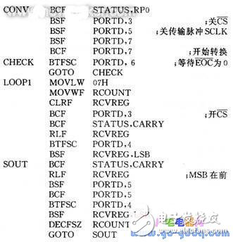
The subroutine for the A/D conversion of the MAX195 is as follows:
5.00MM Wire To Board Connectors
5.00MM Wire To Board Connectors
5.0mm Wire to Board connectors are avialable in different terminations and sizes intended for use on a variety of applications. These connectors provide power and signal with different body styles, termination options, and centerlines. To find the wire to board set required, click on the appropriate sub section below.
5.0mm Wire To Board Connectors Type
5.0mm Terminal
5.0mm Housing
Pitch 5.0mm Wafer Right Angle&SMT Type
5.00MM Wire To Board Connectors
ShenZhen Antenk Electronics Co,Ltd , https://www.atkconnectors.com