This article is mainly about the related introduction of pwm, and focuses on the principle of pwm and the pwm DC motor.
PWM DC motorAt present, in the DC motor control system, a single-chip microcomputer or DSP is generally used as a microprocessor control system. Because the single-chip or DSP control motor occupies a lot of port resources and requires more peripheral components, it affects the stability and stability of the entire system. Reliability has a greater impact. As a kind of industrial control device, programmable controller is known for its strong anti-interference ability and high reliability. With the rapid development of programmable controller, its cost performance is constantly improving.
The main electrical structure of the DC motor servo drive usually adopts the H-bridge, and the speed regulation is mostly through the PWM method. There are roughly three modulation methods: bipolar, unipolar and restricted unipolar. The operating characteristics of the motor and the switching loss and safety of the main circuit are different under different PWM modes. Brushless DC Motor (BrushlessDCMotor, BLDCM) usually adopts a three-phase full bridge main circuit structure and operates under three-phase six-state square wave control. In any state, two switch tubes are controlled by PWM. The PWM modulation method is the same as that of the DC motor. H-bridge PWM modulation is very similar, and both bridge arms are controlled at the same time. The selection of the PWM mode of DC motor speed regulation should be based on the requirements of technical indicators. Usually the DC servo control system mostly adopts bipolar control, which can ensure the continuity of the motor current and other requirements, so as to ensure the rapid response of the motor; for the speed control system, the motor usually works at a higher speed and a larger load. Choose unipolar type or limited unipolar type, so that the main circuit is not prone to through failure, and the working reliability is high. At the same time, the loss, thermal balance, and freewheeling feedback of bridge circuit power devices are also different for different PWM methods.
System software design
System software overall design
The system program mainly includes speed detection and display program, PI control algorithm program and PWM signal generation program. The speed detection and display program realizes the measurement of the actual speed of the motor and displays it in real time using Kingview software. The PI control algorithm program uses PLC's PID function instructions to achieve speed PI control, and uses the output value of the PI controller as the duty cycle of the PWM control signal. The PWM signal generation program uses PLC's PWM function instructions to generate a PWM signal with a certain period and an adjustable duty cycle [2].
The program first initializes the high-speed counter, PWM signal generator and PID parameter table. Then set the timer interrupt, and start the timer to start timing. Next, determine the direction of rotation of the motor. If it rotates forward, determine whether the forward high-speed counter is interrupted, otherwise, determine whether the reverse high-speed counter is interrupted. Once the high-speed counter is interrupted, the current value of the timer is immediately read as the time value for calculating the speed. After that, judge whether a timed interrupt has occurred, and if so, execute the timed interrupt program. The main work of the timed interrupt program is to clear the timer, clear and restart the high-speed counter, calculate the speed, standardize the speed, execute the PID instruction, output value conversion, and execute the PWM instruction , And then output the PWM control signal, otherwise continue to judge whether an interruption occurs [2].
Speed ​​detection program
The detection of the speed is mainly realized by the high-speed counting function of the photoelectric encoder and PLC. The photoelectric encoder and the motor are coaxially connected. Each time the motor rotates one revolution, the two paths of the photoelectric encoder A and B will generate a certain number of orthogonal pulses with a phase difference of 90°. For this reason, the high-speed counter is selected as the A and B two-way orthogonal counting mode. In order to make the high-speed counter work correctly, first write the control word to the control byte of the high-speed counter, use the definition instruction of the high-speed counter to select the working mode for the high-speed counter used, write the set value of the high-speed counter, and clear the current value. Zero, use the interrupt event whose current value is equal to the set value, establish an interrupt connection, and then start the high-speed counter. Start the timer at the same time, when the current value of the high-speed counter is equal to the set value, an interrupt is generated, and the current value of the timer is read out at the same time as the time for generating the set number of pulses, so that the speed can be calculated. In order to improve measurement accuracy and reduce measurement errors, multiple high-speed counters can be used, and each high-speed counter detects the number of pulses in a different time range. In view of the fact that S7-200PLCCPU224 has 4 high-speed counters with A and B two-way quadrature counting methods, the program uses 4 high-speed counters for measurement, and then takes the average value.
Talking about the principle of DC motor pwm1. Pulse width modulation (PWM) is an effective technology to control analog circuits with digital output, especially in terms of controlling the speed of the motor, which can greatly save energy. PWM has strong anti-noise, and has the characteristics of saving space and being more economical. The analog control circuit has the following defects: the analog circuit is easy to drift over time, will produce some unnecessary heat loss, and is sensitive to noise. After using the PWM technology, the above defects are avoided, and the analog signal is controlled in a digital way, which can greatly reduce the cost and power consumption.
2. Brushless DC motor
The DC brushless motor is composed of three parts: the motor, the rotor position sensor and the electronic switch circuit. The DC power supply supplies power to the stator windings of the motor through the switch circuit. The position of the motor rotor is detected by the position sensor and provides a signal to trigger the power switch element in the switch circuit to turn it on or off, thereby controlling the rotation of the motor. In the application example, the magnetic poles rotate, the armature is stationary, and the current commutation in the armature winding is realized by means of a position sensor and an electronic switch circuit. The armature winding of the motor is made of three-phase, the rotor is made of permanent magnet material, and the position sensor connected with the rotor shaft adopts a Hall sensor. Within the range of 3600, there are three installations with a difference of 1200 installations. In order to improve the characteristics of the motor, the motor adopts a two-phase conduction star-shaped three-phase six-state working mode. The switching circuit adopts a three-phase bridge connection method.
Speed ​​regulation and steady speed control
In the speed regulation circuit, the time base circuit LM555 and the pulse width modulator SG1525 are mainly used to complete. LM555 is used to generate a square wave signal with a constant duty cycle and a fixed frequency. SG1525 is a single-chip pulse width modulation controller chip with a 5.1V reference regulated power supply, error amplifier, sawtooth oscillator with an oscillation frequency in the range of 100^400kHz, soft start circuit, shutdown circuit, pulse width modulation comparison Device, RS register and protection circuit, etc. It solves the integration problem of the PWM circuit. In the example, this chip is used to realize the speed regulation of the system. In a specific circuit, the position sensor signal is first shaped to form a waveform with steep front and rear edges and a certain width. After differentiation by the differential circuit, the generated differential pulse triggers the time base circuit LM555 to form a square wave with a duty ratio of 2:1, and the frequency of the square wave is about 200 Hz.
The square wave frequency calculation formula is: f= n * p/ 60 where Y1 is the rated speed of the motor r/min, f is the frequency of the position sensor output signal, and P is the number of pole pairs of the motor. After the square wave is filtered by the filter, it forms a DC voltage and sends it to the pulse width modulator, which is compared with the feedback voltage of the pulse width modulator, and the obtained error signal is used to control the width change of the modulated square wave pulse output by the pulse width modulator. That is, the duty cycle of the PWM output pulse is changed. The voltage applied to the armature winding of the motor is adjusted by the change of the duty cycle. Changing the voltage immediately changes the motor current, and the speed changes according to the magnitude of the current.
Conclusion: In the application example, PWM has the following advantages for the speed control system: the response speed and stability accuracy of the system are relatively good; the pulsation of the armature current is small, it is easy to continue, and there is no need to add filter reactance. Work smoothly; the system has a wide range of speed regulation; it uses fewer components and simple lines.
Detailed pwm applicationPWM is a method of digitally encoding the analog signal level. Through the use of high-resolution counters, the duty cycle of the square wave is modulated to encode the level of a specific analog signal. The PWM signal is still digital, because at any given moment, the full-scale DC power supply is either completely (ON) or completely absent (OFF). The voltage or current source is applied to the analog load in a repetitive pulse sequence of on (ON) or off (OFF). When it is on, it is when the DC power supply is added to the load, and when it is off, it is when the power supply is disconnected. As long as the bandwidth is sufficient, any analog value can be encoded using PWM.
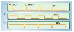
Figure 1 shows three different PWM signals. Figure 1a is a PWM output with a duty cycle of 10%, that is, during the signal cycle, it is on for 10% of the time and off for the remaining 90% of the time. Figure 1b and Figure 1c show the PWM output with a duty cycle of 50% and 90%, respectively. The three kinds of PWM output codes are three different analog signal values ​​with intensity of 10%, 50% and 90% of the full-scale value. For example, assuming that the power supply is 9V and the duty cycle is 10%, it corresponds to an analog signal with an amplitude of 0.9V.
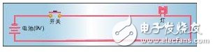
Figure 2 is a simple circuit that can be driven by PWM. In the picture, a 9V battery is used to power an incandescent bulb. If the switch connecting the battery and the bulb is closed for 50ms, the bulb will receive 9V power supply during this time. If the switch is turned off in the next 50ms, the power supplied to the bulb will be 0V. If this process is repeated 10 times within 1 second, the bulb will light up as if connected to a 4.5V battery (50% of 9V). In this case, the duty cycle is 50% and the modulation frequency is 10 Hz.
3. Features
One advantage of PWM is that the signals from the processor to the controlled system are in digital form, without digital-to-analog conversion. Keeping the signal in digital form can minimize the effect of noise. Noise can only affect digital signals when it is strong enough to change logic 1 to logic 0 or change logic 0 to logic 1.
The enhancement of noise resistance is another advantage of PWM over analog control, and this is also the main reason why PWM is used for communication at certain times. Switching from analog signal to PWM can greatly extend the communication distance. At the receiving end, a suitable RC or LC network can filter out the modulated high-frequency square wave and restore the signal to an analog form.
The DC speed regulator is a device that adjusts the speed of a DC motor. The upper end is connected to an AC power source, and the lower end is connected to a DC motor. The DC speed governor converts the AC power into two output DC power sources, one input to the DC motor (stator), and the other Input to the armature (rotor) of the DC motor, and the DC speed regulator adjusts the speed of the DC motor by controlling the DC voltage of the armature. At the same time, the DC motor gives a feedback current to the governor, and the governor judges the speed of the DC motor based on the feedback current, and corrects the armature voltage output if necessary to adjust the speed of the motor again.
The speed control scheme of DC motor generally has the following 3 methods:
1. Change the armature voltage;
2. Change the voltage of the excitation winding;
3. Change the resistance of the armature loop.
The single-chip microcomputer is used to control the speed of the DC motor. Generally, the armature voltage is adjusted by the single-chip microcomputer to control PWM1 and PWM2 to generate variable pulses, so that the voltage on the motor is also a pulse voltage with variable width. According to the formula
U=aVCC
Among them: U is the armature voltage; a is the duty cycle of the pulse (0
The armature voltage of the motor is controlled by the output pulse of the single-chip microcomputer, which realizes the variable speed of the DC motor using pulse width modulation technology (PWM).
Because in the H-bridge circuit, the motor can only be driven when the levels of PWM1 and PWM2 are opposite to each other, that is, when both PWM1 and PWM2 are at the same high level or at the same low level, they cannot work, so the actual pulse width in the above figure Is B,
We set the period of the PWM wave as 1ms, and the duty cycle is adjustable in 100 levels (each level difference is 10%), so that the timer T0 generates a timer interrupt every 0.01ms, and enters the next PWM wave cycle after every 100 times. In the above figure, the duty cycle is 60%, that is, the output pulse is 0.6ms, and the off pulse is 0.4ms, so the armature voltage is 5*60%=3V.
What we are discussing is that it can be rotated forward and reversed. If it only rotates in one direction, we only need to set PWM1 to high or low, and only change the pulse change of another PWM2 level, as shown in the figure below ( Q4 is turned on, Q3 is closed, the motor can only adjust the rotation speed clockwise)
C language code:
#include
#define uchar unsigned char
#define uint unsigned int
sbit K5=P1^4;
sbit K6=P1^5;
sbit PWM1=P1^0;
sbit PWM2=P1^1;
sbit FMQ=P3^6;
uchar ZKB1,ZKB2;
void delaynms(uint aa)
{
uchar bb;
while(aa--)
{
for(bb=0;bb
{
;
}
}
}
void delay500us(void)
{
int j;
for(j=0;j《57;j++)
{
;
}
}
void beep(void)
{
uchar t;
for(t=0;t《100;t++)
{
delay500us();
FMQ=! FMQ; //Generate pulse
}
FMQ=1; //Turn off the buzzer
delaynms(300);
}
void main (void)
{
TR0=0; //Close timer 0
TMOD=0x01; //Timer 0, working mode 1
TH0=(65526-100)/256;
TL0=(65526-100)%256; //100us means 0.01ms interrupt once
EA=1; //Open total interrupt
ET0=1; //Open timer 0 interrupt
TR0=1; //Start timer T0
ZKB1=50; //Set the initial value of duty cycle
ZKB2=50; //Set the initial value of duty cycle
while(1)
{
if (! K5)
{
delaynms(15); //Debounce
if (! K5) //Confirm the button is pressed
{
beep();
ZKB1++; //Increase ZKB1
ZKB2=100-ZKB1; //The corresponding ZKB2 is reduced
}
}
if (! K6)
{
delaynms(15); //Debounce
if (! K6) //Confirm the button is pressed
{
beep();
ZKB1--; //Reduce ZKB1
ZKB2=100-ZKB1; //The corresponding ZKB2 increases
}
}
if (ZKB1 "99)
ZKB1=1;
if (ZKB1《1)
ZKB1=99;
}
}
void time0(void) interrupt 1
{
staTIc uchar N=0;
TH0=(65526-100)/256;
TL0=(65526-100)%256;
N++;
if (N》100)
N=0;
if (N《=ZKB1)
PWM1=0;
else
PWM1=1;
if (N《=ZKB2)
PWM2=0;
else
PWM2=1;
}
//Display: After the motor speed reaches the highest, that is, when N is 1 or 99, press it again to change to 99 or 1.
//The motor rotates in the opposite direction at the highest speed
ConclusionThis is the end of the related introduction about pwm. I hope this article will give you a more comprehensive understanding of pwm.
Related reading recommendation: DC motor PWM control circuit diagram based on UC3637 Related reading recommendation: PWM modulation method of brushless DC motorAdapter Ring,Lens Adapter Ring,Camera Adapter Ring,Filter Adapter Ring
SHAOXING COLORBEE PLASTIC CO.,LTD , https://www.fantaicolorbee.com