This paper introduces an infrared ear thermometer design based on medical digital infrared sensor MLX90615. Based on the infrared temperature measurement principle, the ear thermometer is mainly composed of a digital infrared sensor, a low power CPU, a liquid crystal display and other peripheral circuits. The CPU reads the infrared radiation signal collected by the MLX90615 through the I2C bus, converts it into the corresponding human ear cavity temperature value and displays it on the liquid crystal screen. The experimental results show that the ear thermometer has a resolution of 0.02 ° C and an accuracy of 0.1 ° C, which enables accurate and rapid measurement of ear temperature.
Advantages of Infrared Ear Thermometer Traditional body temperature measurement is a contact measurement using a mercury thermometer. It has the advantages of stable performance and small error, but it has shortcomings such as long measurement time, high risk of cross-contamination, and easy to cause mercury poisoning due to glass breakage. According to Yu Qian, the marketing manager of Shiqiang, the infrared ear thermometer collects the infrared radiation of the ear cavity and the tympanic membrane through the infrared sensor and converts it into a digital signal. The main control CPU unit converts the digital signal into a temperature value and displays it on the liquid crystal screen. Compared with mercury thermometers, infrared ear thermometers have the advantages of high precision, high resolution, fast measurement speed, easy operation, safety and comfort.
The basic principle of the infrared ear thermometer is that the hypothalamus is an important organ for controlling the body temperature of the brain, which is closest to the ear. The average temperature in the deep part of the body changes, the temperature of the ear also changes rapidly, and the inside of the ear is a closed area, which is less affected by external factors, so the ear temperature is closest to the body temperature. The infrared ear thermometer measures the temperature of the human body by measuring the infrared radiation of the human ear canal and the tympanic membrane. The relationship between the radiant energy density and the temperature is in accordance with the Stephen Boltzmann radiation law:
E=εσT4 (1)
Where E is the radiation emission, ie the radiation power emitted per unit area, in W/m3; ε is the radiance of the object; σ is the Stephen-Boltzmann constant; T is the thermodynamic temperature of the object, in K .
Equation (1) shows that the higher the temperature of the object, the greater the radiated power. As long as the temperature of the object and its radiance are known, the radiant power it emits can be calculated. Conversely, if the radiant power of the object is measured, the temperature of the object can be determined. Therefore, an instrument for measuring the temperature of an ear cavity using an infrared sensor to absorb infrared radiation is called an infrared ear thermometer. The infrared sensor uses a series thermocouple, the cold joint is placed on a thick chip substrate, and the thermal joint is placed on the film, and the film absorbs infrared radiation, thereby generating a weak electrical signal. According to the principle of equation (1), the output signal of the infrared sensor is:
Vir(Ta,To)=A(T4 o-T4 a) (2)
Among them, A is the overall sensitivity, and is related to the structural design of the sensor; To is the thermodynamic temperature of the target object, the unit is K, measured by the infrared temperature sensor; Ta is the thermodynamic temperature of the environment, the unit is K, and the additional sensor is needed. Measure the ambient temperature of the target object.
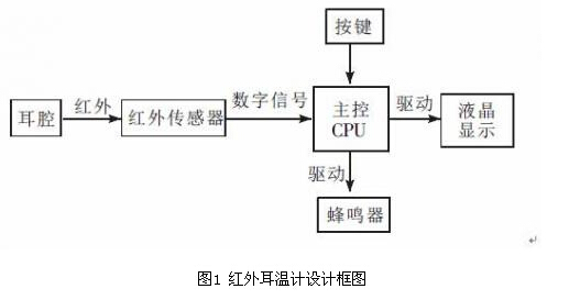
Hardware Design <br> The infrared ear thermometer measures body temperature according to the principle of infrared radiation. The design introduced by Shiqiang is mainly composed of digital infrared sensor, main control CPU unit, liquid crystal display and other peripheral circuits. The design block diagram is shown in Figure 1. When the button is pressed, the digital infrared sensor converts the acquired infrared radiation into a digital signal. After the digital signal collected by the main control CPU is calculated, the temperature value of the ear cavity is displayed on the LCD screen, and the buzzer is sounded.
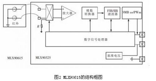
1. The sensor part of the sensor adopts the digital infrared sensor MLX90615, which is mainly composed of infrared thermopile sensor, low noise amplifier, 16-bit analog-to-digital converter and powerful DSP unit. The block diagram is shown in Figure 2. The infrared thermopile sensor converts the collected infrared radiation into an electrical signal, which is amplified by a low noise amplifier and sent to an analog to digital converter. The digital signal output by the analog-to-digital converter is processed by the FIR/IIR low-pass filter and sent to the digital signal processor. The digital signal processor processes the digital signal and outputs the measurement result and saves it in the internal RAM of the MLX90615, which can be passed through SMBus or The PWM mode is read by the master CPU unit.
The MLX90615 offers high accuracy, high resolution, adjustable emissivity, SMBus-compatible digital interface over a wide temperature range, and the medical MLX90615ESG-DAA achieves ±0.1 accuracy over the human body temperature range of 36 to 39 °C. °C. The MLX90615 is widely used in high-precision non-contact temperature measurement, home temperature control, health care, and multiple temperature zone control.
2, the main control CPU
The CPU uses an ARM Cortex-M3-based 32-bit microcontroller EFM32G842F64. The controller has the advantages of high speed and reliability, rich resources, low power consumption, wide temperature range, etc., and is widely used in motor control, medical care, handheld devices and other occasions. The EFM32G842F64 has 64KB of on-chip Flash program memory, 53 general-purpose I/O pins, two 12-bit A/D converters, three general-purpose timers and other peripheral resources, and communication interfaces such as USART, I2C, and SPI. Design requirements for infrared ear thermometers. In this design, the microcontroller EFM32G842F64 mainly performs functions such as judging key input, collecting and processing infrared sensor signals, driving LCD display and buzzer sounding.
3. Liquid crystal display The design display part adopts a universal 1602 character type liquid crystal screen based on HD44780 liquid crystal chip. It means that the displayed content is 16×2, that is, a liquid crystal module capable of displaying two lines of 16 characters and numbers per line. The LCD screen has the advantages of low power consumption, small size, adjustable contrast, built-in character generator, and easy matching processor.
4, other peripheral circuits Other peripheral circuit parts mainly include buttons, buzzers and other parts. The button mainly generates an interrupt signal, which enables the EFM32G842F64 to perform infrared temperature detection. The buzzer prompts the user to end the infrared temperature detection.
Software design 1. Program design software design adopts modular program design, including: initialization module, button detection module, infrared temperature detection module and liquid crystal display module. The program flow is shown in Figure 3. The initialization module mainly completes initialization settings such as reset, general-purpose I/O, interrupt, timer, and I2C. The button detection module mainly detects whether the button is pressed, thereby triggering an external interruption and performing an infrared temperature detection function. The infrared temperature detection module mainly reads the digital infrared sensor MLX90615 according to the I2C bus mode, and converts the digital signal into the ear cavity temperature value according to a predetermined formula. The liquid crystal display module mainly drives the liquid crystal display, and displays the temperature value of the ear cavity on the liquid crystal screen, so that the user can read the data. When the temperature value is displayed on the LCD screen, the buzzer will sound, indicating that the temperature measurement work is over.
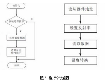
2. The infrared temperature detection module microcontroller EFM32G842F64 integrates the I2C serial interface internally. Therefore, the design uses the SMBus compatible method to read and write the infrared sensor MLX90615. The infrared temperature measurement module mainly includes steps of reading the slave address, setting the emissivity, reading the measured object data, and temperature conversion. The program flow is shown in 4. In the infrared temperature detection module, the EFM32G842F64 reads and writes the digital infrared sensor MLX90615. First, read the subaddress of the slave device MLX90615 in the infrared ear thermometer (the default address of the SMBus slave address is 5Bh). The emissivity in the MLX90615 is factory set to 1, while the human skin emissivity is 0.98. In order to compensate the emissivity of the measured object, the emissivity of the MLX90615 needs to be reset. The RAM unit 07h address of the MLX90615 stores the temperature value of the measured object, so multi-byte data is read according to the I2C bus timing. The formula for converting the temperature value read out in MLX90615 to Celsius is:
To=RAM(07h)0.02-273.15 (3)
Due to the frequent outbreaks of sudden epidemics, the traditional method of measuring body temperature can no longer meet the measurement requirements of human body temperature. Our infrared ear thermometers use a low-power ARM processor and a high-precision digital infrared sensor to simplify hardware and software design tasks, improve design resolution and accuracy, and have clinical care, home care, and more. Wide application prospects. Experiments show that the resolution of the design reaches 0.02 ° C and the accuracy reaches 0.1 ° C, which achieves the purpose of measuring the temperature of the human ear cavity quickly and accurately.
In 2005,our company has transferred from a single PCB manufacturer to a solutioner for PCBA and electronic products by resource integration and huge investment of SMT and X-Ray electronic examing equipment.
Our PCBA Assembly workshop has more than 300 high-quality employees, more than 4,000 square meters of production plants and all are dust-free workshops.
PCBA,PCB SMT Assembly,Printed Circuit Board Assembly,PCBA Production Process,Surface Mount Technology
Huizhou Liandajin Electronic Co., Ltd , https://www.ldjcircuitboard.com