Recently received a project, the need to design a radar product on the locomotive, mainly used for locomotive ranging and collision avoidance in rail transit. Searched online for a period of time, you can choose from Lidar, ultrasonic radar, infrared radar and millimeter wave radar. Compared with the characteristics of each radar, Lidar has the characteristics of long detection distance and accurate detection, but it is easy to be affected by rain and fog, especially snow and dust. This adaptability is not very good in the rail transit industry. Ultrasonic and infrared radars have the advantages of low price and simple design, but are also susceptible to temperature changes, which are very different in the south and north, and the detection distance is limited. The medium detected by the millimeter wave radar is electromagnetic wave, which has the advantages of long detection distance, strong penetrating ability, strong environmental adaptability and good real-time performance, especially those with shorter wavelengths.
As the saying goes, everything is difficult at the beginning! After searching for the solutions of major manufacturers, we finally chose the UMS 24G radar solution. There are several advantages to choosing this solution:
1) The scheme is more flexible, and it is possible to select a single-shot and dual-receiving radar chip with high integration and relatively simple design. Separate devices can also be used to freely combine multiple transceiver combinations, which can detect more accurate and extend the wider detection range.
2) With the industry's only GaAs process, the operating temperature range is -40 degrees -125 degrees, suitable for locomotive working environment.
3) Development tools and reference materials are relatively complete.
In the author's project, the single-chip solution CHC2442-QPG with higher integration is selected. From the internal architecture of CHC2442-QPG in Figure 1, it can be seen that it integrates core functions such as low noise VCO, Tx PA, mixer, receiving LNA and IF amplifier. The functional design of the radar can be completed simply by adding a DSP processing unit. As shown in the schematic diagram of the UMS locomotive 24G radar module, the radar module supports single-shot dual-receiving and one-way video, and communicates with the vehicle control unit via CAN bus and Ethernet.
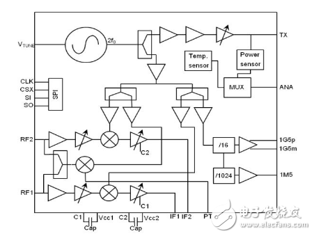
Figure 1: Internal architecture of CHC2442-QPG
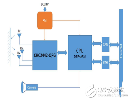
Figure 2: Block diagram of the UMS locomotive 24G radar module
In actual vehicle commissioning, it was found that low-speed driving is prone to false alarms, causing sudden braking. However, in the actual scene, there is no obstacle in front of the car. Then, the signal of the radar front end of the radar module is sampled and analyzed, and it is found that the radar wave reflected by the AP pole and the signal pole of the signal is caused by the chip misreading the obstacle signal in front, thereby outputting an alarm and causing a sudden braking. The analysis is shown in the schematic diagram of the radar detection range in Figure 3.
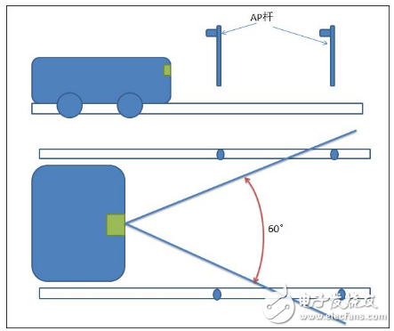
Figure 3: Schematic diagram of radar detection range
After finding the reason, the project team analyzes and discusses it in two directions:
First, the receiving gain of CHC2442-QPG is adjustable, which reduces the receiving gain of the radar when driving at low speed, that is, reduces the receiving sensitivity of the radar to filter off the false obstacles along the track, such as AP poles and signal machines. This direction is easy to implement because the CHC2442-QPG can control the receive gain through the SPI. This receive gain can be adjusted to a range of 24dB, which is wider.
The second is to optimize the antenna design and reduce the width of the lobe in the horizontal direction from the current 60 degrees to 30 degrees. This direction requires redesigning the antenna, reducing the horizontal lobe width from both the layout of the antenna radiating elements and the shape of the individual radiating elements. As shown in the design comparison of the array antenna of Fig. 4, the layout of the array antenna is adjusted from the layout of the left strip to the compact layout of the square on the right. The unit of the antenna is also changed from the original single radiating structure to the symmetrical structure, and a power dividing network is added between the antenna units to ensure a reasonable matching of the impedance. This symmetrical structure can effectively reduce the area of ​​the antenna while keeping the radiation gain from falling.
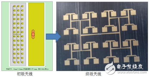
Figure 4: Design comparison of array antennas
Through continuous efforts and optimization, it can be seen from the horizontal lobe width and gain of the final version of the array antenna as shown in Fig. 5 that the horizontal lobe width of the antenna is reduced to 30 degrees, which is doubled compared with the first version, and the gain is maintained at about 21 dBm. . The area is also reduced by about one-third. Finally, the false alarm problem is solved by controlling the receiving gain of CHC2442-QPG and reducing the horizontal radiation lobe width of the antenna.
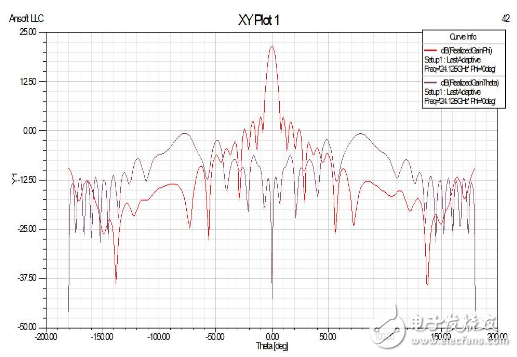
Figure 5: Horizontal lobe width and gain of the final array antenna
Carbon Fiber Rigid Felt Board,Heat Insulation Hard Felt Ring,Conical Carbon Fiber Hard Felt Ring,Carbon Fiber Heat Insulation Hard Felt
HuNan MTR New Material Technology Co.,Ltd , https://www.hnmtr.com