The half-bridge power conversion circuit is a power conversion circuit that can solve the imbalance problem of the push-pull power conversion circuit without adding any circuit complexity. The figure shows a half-bridge power conversion circuit. As can be seen from the figure, in the half-bridge power conversion circuit, one end of the primary winding of the power transformer is connected to the midpoints of the series capacitors C1 and C2. Because of the voltage division of the capacitor, the DC voltage value at this point is about 1/2. The other end of the power transformer is connected to the emitter of the power transistor V1 and the collector of V2 through the capacitor C3. When the power transistor V1 When turned on, this point will be associated with the positive terminal of the input bus, producing a voltage pulse of approximately +Ui/2; when transistor V2 is turned on, this point will be associated with the negative terminal of the input bus, producing approximately one Ui Voltage pulse of /2. When two power transistors are alternately turned on and off, a square pulse with a peak-to-peak value of about Ui is generated on the primary side of the power transformer. Therefore, in the half-bridge power conversion circuit, the maximum withstand voltage of the power transistor is only Push-pull power conversion circuit 1/2. However, it should be noted that just because the power transformer's primary voltage is reduced by 1/2, the operating current of the transistor will increase under the same power output condition.
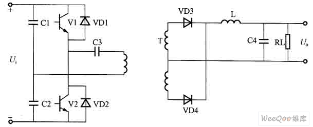
Figure half bridge power conversion circuit
Bluetooth Speaker,Bluetooth Portable Speaker,Wireless Mini Bluetooth Speaker,Home Mini Bluetooth Speaker
Dongguan Yuhua Electronic Plastic Technology Co.,Ltd , https://www.yuhuaportablefan.com