With the rapid development of my country's smart grid, smart energy meters have been installed in large numbers. For single-phase smart meters, they are mainly used for residential electricity metering. At present, most of the products are of class 2.0, and some of the more demanding ones are class 1, that is, the relative error is 2% or 1%. For three-phase smart meters, they are mainly used in industrial electricity measurement. At present, most of the products are level 1 and 0.5S, and some of the more demanding ones are 0.2S, that is, the relative error is 1%, 0.5% or 0.2%. At the same time, because it is applied to non-linear load occasions such as industrial or agricultural irrigation and drainage, the requirements for phase error are also higher. Therefore, how to improve the measurement accuracy of non-linear loads is a difficult point in the design of smart meters.
Aiming at the above problems, the present invention provides a three-phase smart meter nonlinear load accurate measurement analysis design method that improves the performance of the metering chip and the nonlinear load measurement accuracy.
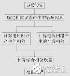
Figure is a flowchart of the invention
The technical scheme of the present invention includes the following steps: S1: parameter setting, so that the voltage sampling loop and the current sampling loop are in the differential amplification linear region of the metering chip; adjusting the voltage sampling circuit parameters so that the peak value at 120% Un is in the metering chip Within 60%-80% of the maximum differential input voltage range, select the voltage sampling resistor; adjust the current sampling circuit parameters so that the peak value of Imax is within 40%-60% of the maximum differential voltage range of the measurement chip, select current sampling Resistance; S2: Determine the influencing factors of the phase error, including the phase shift produced by the voltage loop and the composite phase shift produced by the current loop; S3: Calculate the phase shift produced by the voltage loop; select the capacitor according to the voltage sampling resistor selected in step S1 , And then calculate the capacitance and capacitance, impedance and the voltage divider ratio of the voltage loop in turn to obtain the phase shift produced by the voltage loop; S4: calculate the synthetic phase shift produced by the current loop; determine the influencing factors of the synthetic phase shift produced by the current loop , Including the phase shift produced by the current transformer, the phase shift produced by the current loop filter capacitor and the phase shift produced by the amplification sampling and multiplication operation, and the composite phase shift is obtained by adding the three phase shifts; S41: Calculating the phase shift produced by the current transformer Phase shift; select according to the accuracy level of the current transformer and the different rated current; S42: calculate the phase shift produced by the current loop filter capacitor; calculate the capacitance and the current loop's voltage divider ratio in turn, so as to obtain the current loop Phase shift; S43: Calculate the phase shift generated by the amplification sampling and multiplication operation; Set the high-pass filter and the phase correction network on the three pairs of current sampling ends of the metering chip respectively; S5: Calculate the integrated phase error; pass the voltage in step S3 The phase shift generated by the loop and the composite phase shift generated by the current loop in step S4 are added together; S6: correction selection; through the comprehensive phase error in S5, combined with the phase correction register of the metering chip, select the corresponding current transformer Make corrections.
Steps S1 and S2 also include the step of judging the measurement error by the active energy meter and the step of judging the measurement error by the reactive energy meter.
The present invention analyzes and judges to improve the measurement accuracy of the measurement chip from three aspects, namely:
1. The nonlinearity in the differential amplification part of the measurement chip is analyzed;
2. Theoretically analyze the reasons for the low measurement accuracy under nonlinear load;
3. The reasons for the phase error of the electric energy meter are analyzed.
Among them, it is especially related to the analysis of the phase error generated by the amplification and sampling link of the metering chip. By analyzing the cause of the phase error, the error generated by the input loop is first included, that is, the phase shift between the voltage input loop and the current input loop is different. Caused. Therefore, to improve the phase error performance of the electric energy meter, the phase error generated by the input loop must be minimized as much as possible, thereby improving the measurement accuracy.
Feed Through Terminal Block Section
Feed Through Terminal Block.
In the electrotechnics, the terminal refers to the terminal and is designed to run through the terminal production. The type is divided into single hole, double hole, socket, hook, etc. from the material, copper silver plating, copper zinc plating, copper, aluminum, iron, etc. their functions are mainly to transmit electrical signals or conduct electricity. The unit of terminal block is "bit", and one wiring bit is "bit". Usually the so-called table is the serial number of the terminal, which has different definitions in different applications. "Jie" and "bit" have the same meaning, but they are called differently. Groups are made up of sections.
Feed Through Terminal Block
ShenZhen Antenk Electronics Co,Ltd , https://www.antenkconn.com