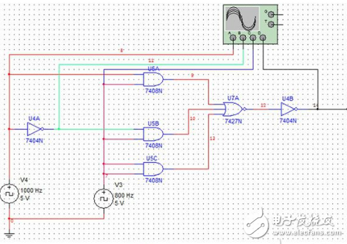
According to the different characteristics of logic functions, digital circuits can be divided into two categories, one is called combinational logic circuit (referred to as combination circuit), and the other is called sequential logic circuit (referred to as sequential circuit). The logical function of the combinational logic circuit is that the output at any time depends only on the input at that moment, regardless of the original state of the circuit. The logic function of the sequential logic circuit is that the output at any time depends not only on the input signal at the time, but also on the original state of the circuit, or related to the previous input.
1. Half adder and full adder 1 half adder The two numbers A and B are added together, and only the sum of the original bits is sought. The number of digits sent by the low position is called "half plus".
The logic circuit that completes the half-plus function is called a half adder. In actual binary addition, the two addends are generally not one bit, so the half adder that does not consider the low carry does not solve the problem.
Adding the two numbers not only considers the sum of the bits, but also considers the number of digits from the low position, called "full plus". The logic that implements this function is called a full adder.
2. Adder A circuit that implements the addition of multi-bit binary numbers is called an adder. There are two types of serial carry adders and super forward carry adders depending on the carry mode.
1 four-bit serial adder: such as T692. Advantages: The circuit is simple and the connection is convenient. Disadvantages: The operation speed is not high. The calculation of the highest bit must wait until all the low bits are completed according to this operation, and the carry signal can be sent. In order to increase the speed of the operation, a super forward position method can be employed.
2 super-advanced adder: the so-called super-advanced bit, that is, when adding, the carry signal of each digit is directly generated by the input binary number.
The process of representing a particular signal by code is called encoding; the logic that implements the encoding function is called an encoder. The input to the encoder is the encoded signal and the output is a set of binary codes corresponding to the input signal.
2. Ordinary encoder 1 three-bit binary encoder: binary encoder: A circuit that encodes m=2n general signals when using n-bit binary code.
2 two decimal encoder: A circuit that encodes 0 to 9 decimal digits into binary code. There are 2n kinds of n-bit binary codes, and m≤2n signals can be encoded. Since the input of the binary decimal encoder is ten decimal numbers, a four-digit binary code representation should be used. Take 10 from 2n=16 binary codes to represent 0~9. This is a decimal number. There are many programs. The most commonly used is the 8421BCD code. In the two-digit decimal encoder, the input signals representing 0 to 9 are mutually exclusive, and the working principle and design process are identical to those of the three-bit binary encoder, and are not repeated.
Definition: Allows several signals to be input simultaneously, but only encodes the signal with the highest priority, regardless of the low level signal. Such a circuit is called a priority encoder.
1) Basic concept definition: The process of converting the binary code according to the willingness to convert the corresponding output signal is called decoding. The logic circuit that completes the decoding function is called a decoder. The n inputs of the decoder, m outputs should satisfy 2n ≥ m. The decoder has a binary decoder, a binary decoder, a digital display decoder and the like.
2) The binary decoder converts the various states of the binary code into the output of the corresponding signal according to its original meaning. This circuit is called a binary decoder. In the binary decoder, if the input code has n bits, the output signal is 2n. So it can translate the full state of the input variables. (sometimes called a variable decoder, or a minimum item generator.
The data distributor (DemulTIplexer), also known as the demultiplexer, has only one data input, but has 2n data outputs. Data is sent to one of the 2n data outputs based on different combinations of n select inputs. From its role, it is very similar to a multi-position switch. From the perspective of logic function, it is just the opposite of the data selector.
2 . Decoder as data distributorAny decoder with an enable control can be used as a data distributor.
3. Multi-channel signal time-sharingThe combination of the data selector and the data distributor enables time-divisional transmission of multiple signals. Principle: When the input C2C1C0=001 is selected, the data selector sends the state of XIN1 to the output. For the data distributor, the sent XIN1 is assigned to the XOUT1 terminal. The signals are not transmitted at the same time, but the transmission line is reduced.
When comparing two 1-bit binary numbers, there are 4 possibilities and 3 results.
Let: A=A3A2A1A0, B=B3B2B1B0
Use li =1 to indicate Ai>Bi;
Mi =1, indicating Aigi =1, indicating Ai=Bi.
When comparing, it should start from high. If the high level is compared with the result, the low position is no longer needed. When the highs are equal, go to the lower ones. ;

Fan Motor,Blower Motor,Condenser Fan,Condenser Fan Motor
Wentelon Micro-Motor Co.,Ltd. , https://www.wentelon.com