1 Introduction
Pulse measurement is a measurement that detects the presence or absence of a pulse. When there is a pulse, it blocks light, and when there is no pulse, it transmits light. The sensors used are infrared receiving diodes and infrared emitting diodes. The pulse measurement used for sports measurement generally has two modes: finger vein and ear vein. These two measurement methods have their own advantages and disadvantages. The pulse measurement is convenient and simple. However, because there are more sweat glands on the fingers, the finger clamps are used all the year round. The pollution may reduce the measurement sensitivity. The ear vein measurement is relatively clean, and the sensor uses environmental pollution. Less, easy to maintain. However, because the ear veins are weak, especially when the season changes, the measured signal is significantly affected by the ambient temperature, resulting in inaccurate measurement results.
2 pulse signal picking
The pulse signal pickup circuit is shown in Figure 1. IC1A is connected as a unity gain buffer to generate a reference voltage of 2.5V.
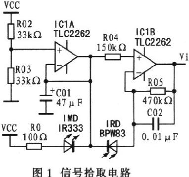
The infrared receiving diode can generate electric energy under the illumination of infrared light, and a single diode can generate O.4 V voltage and 0.5 mA current. The BPW83 infrared receiving diode and the IR333 infrared emitting diode have a working wavelength of 940 nm. In the finger clip, the infrared receiving diode and the infrared emitting diode are placed opposite each other to obtain the best directivity. The larger the current in the infrared emitting diode, the smaller the emission angle, and the greater the intensity of the emission. In Figure 1, the RO selection of 100 Ω is based on the sensitivity of the infrared receiving diode to sense infrared light. When R0 is too large, the current through the infrared emitting diode is too small, and the BPW83 type infrared receiving diode cannot distinguish between the pulse and the pulseless signal. On the contrary, if R0 is too small, the current passing through is too large, and the infrared receiving diode cannot accurately distinguish the signal with and without pulse. When the infrared light emitted by the infrared emitting diode directly illuminates the infrared receiving diode, the potential of the inverting input terminal of IC1B is greater than the potential of the non-inverting input terminal, and Vi is “Oâ€. When the finger is in the measurement position, two situations occur: one is the pulse-free period. Although the finger blocks the infrared light emitted by the infrared emitting diode, due to the dark current in the infrared receiving diode, a dark current of 1 μA causes the Vi potential to be slightly lower than 2.5 V. The second is the pulse period. When there is a beating pulse, the blood pulse makes the finger translucency worse, the dark current in the infrared receiving diode decreases, and the Vi potential rises.
From this point of view, the so-called pulse signal pickup is actually obtained by the infrared receiving diode, the weak change of the dark current when there is a pulse and no pulse, and then amplified by IClB. The picked up signal is a voltage signal of about 2 μV.
3 signal amplification
The low-pass amplifier is designed according to the calculation of the maximum pulse rate of the human body pulse after exercise for 240 times/minute, which is composed of IC2A and C04, as shown in Fig. 2. The corner frequency is determined by R07, C04, R08 and C05, and the magnification is determined by the ratio of R08 and R06.

According to the transfer function of the second-order low-pass filter,
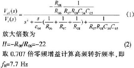
The low frequency characteristics are satisfactory considering that the human pulse is up to 4 Hz.
It should be noted that the above analysis is made under the condition of ignoring C03. If you consider C03, then:

It can be seen that C03 has no influence on the analysis of frequency characteristics, and its function is only to block the straight.
The secondary amplifier and comparator are shown in Figure 3. Rpll is used to adjust the amplification factor of the system, and C06 is used to prevent the amplifier from self-exciting. With secondary amplification, the zero drift is not very noticeable, around O.1 V. Therefore, the threshold voltage of the comparator is designed to be O.25 V to ensure that the interference signal is filtered out. The advantage of using a comparator is that it can effectively overcome the effects of zero drift and improve the accuracy of the measurement.

4 waveform shaping
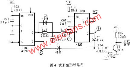
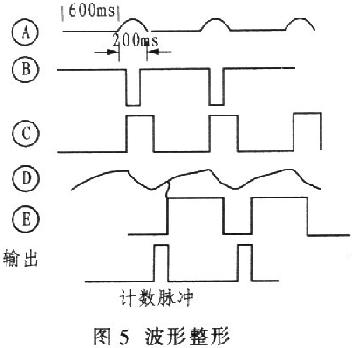
The waveform shaping circuit is shown in Figure 4. IC3A is a CD4528 monostable multivibrator with an effective pulse width of 0.05 s. Its width is determined by R22 and C20. IC3B also forms a monostable multivibrator with a pulse width of 240ms. D2, Dl and T3 form a NOR gate. When both C and E are low, the signal amplifier output is high. The purpose of this circuit is to output a narrow pulse at the output, and any signal will not interfere with the output for the time determined by R13 and C07. The length of the charging time of R23 and C21 determines the width of the counting pulse, which is generally not expected to be too wide. The waveform shaping timing is shown in Figure 5.
5 Conclusion
When the amplifier is used in a cluster pulse meter, be sure to pay attention to the interaction between the different signal channels. It is recommended to separate the power supplies of the individual amplifiers. In addition, the measurement channel requires a switching circuit. When the finger clamp is suspended, the switching circuit turns off the monostable circuit, cutting off the signal path, and preventing the disorder.
The production practice of several years proves that the amplification processing circuit is stable and reliable. Here are some of the experiences I gained in the design.
The use of two-stage amplification is better than three-stage amplification. The zero-point drift of individual three-stage amplifier boards is large enough to reach full scale, making measurement inaccurate. The amplification factor of each single-stage amplifier should preferably not be greater than 30 to avoid self-oscillation.
The high frequency corner frequency of this signal amplifier is determined by C05, C04, R07, R08 and R06. C05 and C04 are usually selected from polypropylene capacitors or polycarbonate capacitors. R07, R08 and R06 are usually selected as metal film five-color ring resistors.
IClA, R02 and R03 form a voltage follower with a design value of 2.5 V. The accuracy is determined by R02 and R03. It is best to use a metal film five-color ring resistor.
The leakage current of the DC blocking capacitor C03 is small, and the tantalum electrolytic capacitor is preferred.
IClA and IC1B use an op amp with a small bias current and a small input offset voltage. Considering the price/performance ratio, I used TLC2264 and TLC2262. funcTIon ImgZoom(Id)//Reset the image size to prevent breaking the table { var w = $(Id).width; var m = 650; if(w < m){return;} else{ var h = $(Id) .height; $(Id).height = parseInt(h*m/w); $(Id).width = m; } } window.onload = funcTIon() { var Imgs = $("content").getElementsByTagName( "img"); var i=0; for(;i
Plug-In Connecting Terminals,Insulated Spade Terminals,Cable Connector Double Spade Terminals,Vinyl-Insulated Locking Spade Terminals
Taixing Longyi Terminals Co.,Ltd. , https://www.lycopperlugs.com