The LED display based on mobile data uses the widest and most stable GSM/GPRS/CDMA/PHS network at present, and the content of the LED display can be updated conveniently in real time through short messages in any place with mobile network coverage. , It effectively solves the trouble of updating the data of the LED display screen and the difficulty of being unable to monitor, and reduces the workload of the management department. With the development of mobile communication technology and the further promotion of the application range of LED display screens, such LED display screens based on mobile data have greater application value.
As an information display device, LED electronic display screens are mainly used to broadcast advertisements, news, notifications, weather forecasts, time, stock information, flight information, ticket information, etc., in stop signs, traffic intersections, buses, ticket halls, and business Halls, waiting halls, securities companies, airports, sports, weather, traffic control and other places have been more and more used, and have broad application prospects.
However, traditional LED display screens use wired communication to transmit data, which is severely restricted by geographical areas and wiring. If there are a large number of LED displays working at the same time, it becomes very troublesome to transmit updated data for the LED display, and without other additional control equipment, the management department of the LED display cannot monitor the actual status of the LED display. Operating conditions.
1 System composition and principleThis kind of LED display screen system based on mobile data is composed of four parts: GSM wireless transceiver module, MCU (microcontroller), LED drive circuit, and LED display screen. The principle block diagram is shown as in Fig. 1.
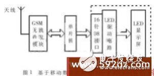
The control center of the system is MCU (Single Chip Microcomputer). This design uses ATMEL's AT89C51 chip. It controls the GSM wireless module to send and receive mobile data through the serial port, and controls the LED drive circuit and the display screen to display the content that needs to be displayed in an appropriate way. The GSM wireless transceiver module uses Siemens' TC35i and is equipped with a common SIM card on the market. It is responsible for receiving the display content sent by legitimate users through the mobile network, and transmitting the status data of the LED display to the user through the mobile network. The LED drive circuit and the display screen are basically the same as the traditional method [1, 2]. The LED unit board with "16 PIN 08 interface" is used, which can be spliced ​​into the required screen size.
When using it, the user only needs to edit the content that he wants to display on the LED screen on his mobile phone or computer in the text message format, and then send it to the number corresponding to the SIM card inserted in the TC35i module like a normal text message. After the TC35i module with SIM card receives the sent message, it first checks whether the sender of the message is a legitimate user. If it is not a legitimate user, TC35i discards the short message; if it is a legitimate user, it takes out the content to be displayed, and controls the LED screen to display the information in the required manner. At the same time, TC35i can send the status data of the LED screen to legitimate users in SMS format. In this way, the two-way real-time transmission of display content and status data is realized by using the mobile communication network.
Considering the simplicity, this article uses a 32×64 dot matrix LED unit board to display 16×16 dot matrix Chinese characters as an example to illustrate the system principle. As for the larger size of the LED screen, just cascade multiple similar LED unit boards through the "16 PIN 08 interface" in turn.
2 hardware implementation2.1 The hardware interface circuit of TC35i module and one-chip computer
The transmission and reception of mobile data in this system all rely on the TC35i module. The TC35i module integrates radio frequency circuit and baseband processing. It can work in two frequency bands of GSM 900 MHz and DCS 1 800 MHz. It uses RS232 serial port to connect with MCU (microcontroller). Its RS232 data interface complies with GSM07.05 and GSM07.07 specifications. Use the standard AT command set. The module is connected to the antenna through the 50 Ω antenna connector, and also through the 40-pin ZIF connector to realize the connection of the power supply and the SIM card holder, as well as the two-way transmission of commands, data, voice signals and control signals [3].
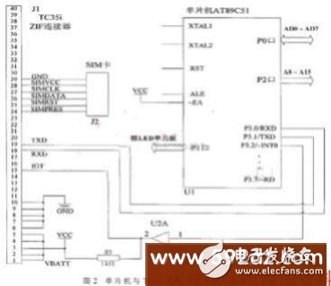
Figure 2 shows the key part of the MCU and TC35i interface.
It should be noted that after the system is powered on, in order to make the TC35i enter the working state, a low pulse with a delay greater than 100 ms must be added to the IGT pin, and the duration of the level drop cannot exceed 1 ms. After startup, IGT should remain high (3.3 V). When driving IGT, the supply voltage of TC35i cannot be lower than 3.3 V, otherwise TC35i cannot be activated. In addition, the SIMPRES pin of the ZIF connector is used to detect whether the SIM card is inserted properly. If the connection is correct, the SIMPRES pin outputs a high level, otherwise it is a low level.
2.2 MCU and LED display drive circuit
Since only the internal code of Chinese characters is obtained through the mobile network short message, and the LED screen displays the dot matrix information of the Chinese characters, the GB2312 Chinese character dot matrix font library must be stored in this system, and a large number of displays need to be stored when the LED screen displays Data, so 64 KB of RAM (62256) and 512 KB of Flash memory (29F040) are expanded on the periphery of the microcontroller AT89C51. Among them, 29F040 stores dot matrix fonts (HZK16, ASC16) and Unicode to GB2312 code table, and 62256 is used as display buffer. After receiving the short message, the one-chip computer first converts the information to be displayed into GB2312 code, and then reads the corresponding dot matrix information from 29F040 and stores it in 62256 when displaying it.
The P1 port of the single-chip microcomputer is used to control the display of the LED screen, among which pins P1.0~P1.3 output 4-bit row selection signals A, B, C, D, and ABCD changes from 0000 to 1111, and scans 1 to 16 points line by line. , Display the display data in sequence; P1.4 pin outputs the shift clock signal SHCLK, so that the display data can enter the LED unit board in sequence; P1.5 pin outputs the latch signal STB, so that the display data can be output stably; P1.6 pin Output the display data R1 of the upper 16 rows of the LED unit board, and output the display data R2 of the lower 16 rows of the LED unit board at pin P1.7.
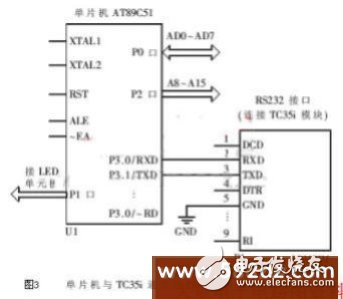
When the 32×64 dot matrix LED unit board is used to display 16 dot matrix Chinese characters, it can display 2 lines with 4 Chinese characters per line. Its composition circuit is shown in Figure 3. The row drive circuit uses 2 74HC138 chips, and the column drive circuit for the upper and lower 16 rows uses 8 74HC595 chips. The specific display adopts dynamic scanning mode. The 4-bit row selection signals A, B, C, D output by the single-chip microcomputer are decoded by 2 74HCl38 and then scan the 1-16 and 17-32 rows of the LED unit board row by row; the upper 16 rows The display data R1 of the display data R1 and the display data R2 of the next 16 rows are input into their respective 74HC595 in sequence under the action of the same shift clock signal SHCLK, and finally output stably at the parallel output terminal of the 74HC595 under the action of the common latch signal STB.
In the actual production of LED unit boards, 4953 chips are often added to the line scan line output by the 74HCl38 chip to increase the driving capability.
3 program design3.1 Short message sending and receiving control
The single-chip microcomputer controls the TC35i module to initialize and send and receive short messages through AT commands. There are three modes for the control of short messages: Block mode, PDU mode and Text mode. Text mode does not support Chinese, and the use of Block mode requires driver support from the mobile phone manufacturer. This system uses PDU mode to receive and send short messages.
After the system is powered on, the TC35i is initialized first, the contents mainly include:
(1) Set the SMS center number AT+CSCA="+8613800250500"
(The number is set differently in different regions).
(2) Set the short message format AT+CMGF=0 (0 represents PDU format).
(3) Set the location where the short message is stored AT+CPMS = "SM" (SM means to store the short message in the SIM card).
(4) Set SMS arrival notification AT+CNMI=1, 1, 0, 0, 1. This command enables the module to send the command +CMTI: "SM", INDEX (information storage location) to the microcontroller after the short message arrives.
During system operation, the single-chip microcomputer controls the TC35i module to receive or send short messages through AT commands. The command format is as follows:
(1) Read the short message command AT+CMGR=INDEX.
(2) Send the short message command AT+CMGS=<length><CR>.
(3) Delete the short message command AT+CMGD=INDEX.
(4) SIM card status query command AT^SCKS.
The received and sent short messages are processed by the microcontroller in the form of PDU string data. The PDU string is composed of numbers "0" ~ "9" and letters "A" ~ "F", which are hexadecimal numbers or BCD code decimal numbers . The PDU string contains not only the displayable message itself, but also a lot of other information, such as SMS service center number, destination number, reply number, encoding method, and service time. The structure of the PDU string sent and received is not exactly the same. The following two examples illustrate the structure and arrangement of the PDU string.
Example 1: Receive. The SMSC number is +8613800-250500, the other party's number is 13851872468, and the message content is "Hello!". The PDU string read by the MCU from the TC35 module is 08 91 68 31 08 20 05 05 F0 84 0D 91 68 31 58 81 27 64 F8 00 08 30 30 21 80 63 54 80 0*F 60 59 7D 00 21.
Example 2: Send. The SMSC number is +8613800-250500, the other party's number is 13851872468, and the message content is "Hello!". The PDU string sent by the microcontroller to the TC35 module is 08 91 68 31 08 20 05 05 F0 11 00 0D 91 68 31 58 81 27 64 F8 00 08 00 0*F 60 59 7D 00 21.
3.2 LED display control program
The dynamic scanning function of the LED is realized by using the timer 0 interrupt of the microcontroller. The initial value of timer 0 is set to meet the requirement of interrupting more than 1,000 times per second, and each interruption scan displays one line, so that each line is scanned at least 60 times per second. According to the persistence effect of human eyes, a more ideal display effect is achieved.
Timer 0 interrupt service routine:
void int0(void) interrupt 1
{
TR0=0; //Turn off timer T1
TL0=0x80; //Set the lower 8 bits of the initial value
TH0=0xff; //Set the upper 8 bits of the initial value
TR0=1; //Start timer T1
if(i
//Scan 1 to 16 lines in sequence
{
P1_5=0; //Close HC595 latch
while(z
//The number from left to right, ranging from 0 to 7.
//Each piece of HC595 goes through 8 cycles,
//Realize the serial/parallel conversion of 8-bit data
{a=disp[i*2+k];//take the 16-line 8-bit display data a
b=disp[i*2+k+128]; //Remove 8 bits of 16 lines
//Display data b
if(z%2!=0) k+=32-1;
else k++;
while(j
//Move the feet into the upper HC595 one by one,
//Put b through P1.7 in turn
//Move into the HC595 below
{
P1_4=0; //Pull the P1.4 port line low,
//Generate shift pulse SHCLK
if((a&au)>0) //fake serial port P1.6, output 16 lines
//The display data a
P1_6=1;
else
P1_6=0;
if((b&au)>0) //fake serial port P1.7, output the next 16 lines
//The display data b
P1_7=1;
else
P1_7=0;
P1_4=1; //Set the P1.4 port line high to produce shift
//Pulse SHCLK
au=au
j++;
}
j=0;
au=0x01;
z++;
}
k=0;
z=0;
}
P1=(P1&0xf0)|i; //Generate 4 bits through P1.0~P1.3
//Line scan signal ABCD
P1_5=1; //Open 595 latch
i++;
if(i==16) i=0;
}
4 PROTEUS simulation implementationThis design uses Keil μVision2 and Proteus software to realize the software design and hardware simulation debugging of the system.
Proteus software can simulate a variety of commonly used single-chip microcomputers including 51 series and their peripheral circuits (such as LCD, RAM, ROM, keyboard, motor, LED, etc.), and is currently the best tool for simulating peripheral devices of single-chip microcomputers. In the simulation, you only need to draw the peripheral control and LED display drive circuit of the single-chip microcomputer in the Proteus software, and then set the crystal frequency in the properties of the single-chip microcomputer chip, and save the .HEX file generated by the source program written by Keil C51 to the chip. You can simulate and debug [4, 5]. During the simulation process, if there is a hardware problem, you can directly modify it in Proteus ISIS, if there is a software problem, you can directly modify it in Keil μVision2. Satisfactory results can be obtained through the joint debugging of Keil and Proteus, avoiding the direct production of physical objects from the beginning, thus shortening the development cycle of the system and reducing the cost of development and debugging.
There is no GSM module TC35i in the Proteus software, but the serial port simulation function provided by Proteus can be used to realize the simulation debugging of the communication between the single-chip microcomputer and the TC35i module. The concrete circuit is shown as in Fig. 3. The serial port (P3.0, P3.1 pin) of the single-chip microcomputer is connected to the TC35i module through the serial interface device COMPIM (the TC35i module is not shown in the figure). First, use the virtual serial port software VSPDXP (Virtual Serial Port Driver XP) to set up two interconnected virtual serial ports COM3 and COM4 on the simulated host, and then start the "Serial Port Debug Assistant" software, and set the serial port to COM4, ​​baud rate Choose 4 800 b/s, then set the COM3 port of the COMPIM device in the Proteus simulation circuit, and choose 4 800 b/s as the baud rate. It must be noted that the setting value of the baud rate in COM3 and COM4 is the same as the setting value of the baud rate in the MCU software, here are both set to 4 800 b/s, and finally run the Proteus simulation, then you can use the "serial port debugging" The "Assistant" software simulates the data format output by the TC35i and sends data to the microcontroller. For example, under normal circumstances, if you send the hexadecimal data string "08 91 68 31 08 20 05 05 F0 84 0D 91 68 31 58 81 27 64 F8 00 08 30 30 21 80 63 54 80 0*F from the "serial debugging assistant" under normal circumstances 60 59 7D 00 21", the LED screen in the simulation circuit will display "Hello!". The AT command string sent by the microcontroller to the TC35i module will be displayed in the receiving window of the "Serial Debug Assistant" in real time. If it is not correct, you can use virtual instruments such as virtual serial port terminals in the Proteus software and graphs for code-level tracking and debugging.
After slightly modifying the successfully simulated circuit, the actual circuit is produced, and the program is solidified into the actual single-chip microcomputer chip. The actual running result obtained is completely consistent with the simulation result of Proteus.
The LED display based on mobile data uses the mobile communication network to update the content of the LED display in real time, avoiding the trouble of laying lines in the original system or constructing special wireless transceivers, effectively reducing the system cost, and it is useful for staying away from office places, especially outdoors The design of the LED display screen provides a new idea. At the same time, in the process of developing this system, make full use of the powerful functions of the embedded system software and hardware design simulation platform Proteus software to carry out virtual development of the system. After success, the actual production will be carried out, which greatly improves the development efficiency and reduces the development cost. And the development of embedded systems has practical significance.
Ac Charging Pile,11Kw Ac Charging Pile,Double Gun Pile,Split Charging Pile
Guangdong ChongWei Technology Ltd. , https://www.chongweitech.com